Energy reduction in a hematite processing plant should not begin with a list of fashionable technologies. It should begin with the plant’s mass balance, operating power requirements and metallurgical targets. A change that lowers mill power but also reduces iron recovery is not necessarily an improvement.
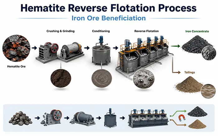
This article uses the design data of a 200 TPH hematite beneficiation line to identify the main electrical loads and establish practical optimization priorities. The line includes two-stage grinding and cyclone classification, low-intensity magnetic separation, two stages of vertical-ring pulsating high-gradient magnetic separation, concentrate thickening and disc filtration, and tailings thickening and pressure filtration.
The figures used in this article are design values supplied for equipment selection. They are not presented as measured production results. Actual energy performance must be verified using electricity meters, operating records and a controlled plant sampling program.
1. Start with the Production and Metallurgical Targets
The plant is designed to process 200 tonnes of run-of-mine ore per hour, equivalent to 4,800 tonnes per day when operating continuously for 24 hours.
| Stream | Yield | Fe grade | Iron recovery | Production |
|---|---|---|---|---|
| Concentrate | 81.49% | 64.21% | 91.12% | 162.98 t/h or 3,911.45 t/d |
| Tailings | 18.51% | 27.53% | 8.88% | 37.02 t/h or 888.55 t/d |
| Feed | 100.00% | 57.42% | 100.00% | 200.00 t/h or 4,800.00 t/d |
The concentration ratio is approximately 1.23 tonnes of feed per tonne of concentrate.
The iron mass balance is also consistent. The feed contains approximately 114.84 tonnes of iron per hour, while about 104.65 tonnes report to the concentrate and 10.19 tonnes report to the tailings.
These figures establish the boundaries for energy optimization. Every proposed change should be evaluated against the target concentrate grade of 64.21% Fe and iron recovery of 91.12%, rather than against power reduction alone.
For more information about the overall beneficiation route, see the hematite processing solution.
2. Convert the Equipment List into an Energy Baseline
The scheduled operating load in the equipment table is 5,398 kW. At the design throughput of 200 t/h, this produces a theoretical load-to-throughput ratio of:
5,398 kW ÷ 200 t/h = 26.99 kWh per tonne of feed
Based on concentrate production, the corresponding theoretical figure is:
5,398 kW ÷ 162.98 t/h = 33.12 kWh per tonne of concentrate
These figures can be used as preliminary design benchmarks, but they should not be interpreted as the plant’s actual specific energy consumption.
Nameplate or scheduled power is not the same as average power draw. Motor loading, variable-frequency operation, standby equipment, downtime, ore hardness and auxiliary systems all affect the electricity measured during production.
After commissioning, the actual energy baseline should be calculated using:
Actual specific energy consumption = metered electricity during the test period ÷ dry tonnes of ore processed during the same period
The plant should record concentrate output, feed grade, concentrate grade, iron recovery, particle size and product moisture during the same test period. Without synchronized data, an apparent reduction in energy consumption may simply result from a change in ore characteristics or product quality.
3. Identify the Largest Electrical Loads
The design power distribution shows where optimization is most likely to generate meaningful results.
| Process area | Scheduled operating load | Share of total load | Main equipment |
|---|---|---|---|
| Two-stage grinding | 3,450 kW | 63.9% | Two MQY3660 mills and two MQG2745 mills |
| Slurry and return-water pumping | 786 kW | 14.6% | Cyclone, thickener, filter press and return-water pumps |
| Magnetic separation | 540 kW | 10.0% | CTB1500×3000 separators and SLon-3000 separators |
| Other listed drives | 622 kW | 11.5% | Feeding, conveying, screening, thickening, filtration and agitation |
Grinding and pumping together account for approximately 78.5% of the scheduled operating load.
The first energy audit should therefore focus on the mill–cyclone–pump circuit. Replacing a small conveyor motor may be relatively easy, but it cannot produce the same system-level benefit as preventing unnecessary material from recirculating through a 1,250 kW ball mill.
4. Optimize the Two-Stage Grinding Circuit as One System
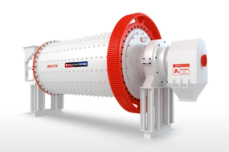
The first grinding stage uses two MQY3660 ball mills with a combined scheduled operating load of 2,500 kW. The second stage uses two MQG2745 ball mills with a combined load of 950 kW.
The mills are paired with first-stage 4 × FX500 cyclone arrangements and second-stage 10 × FX350 cyclone arrangements.
The objective is not simply to lower the amperage of the mill motors. It is to produce the coarsest material that still exposes enough hematite for the downstream magnetic separation circuit to achieve the required concentrate grade and recovery.
The grinding circuit audit should record:
Dry feed rate to each mill
Mill power draw and motor load
Feed and discharge pulp density
Cyclone feed pressure
Cyclone feed density
Overflow and underflow particle-size distributions
Circulating load
Grinding-media size distribution and charge
Liner condition
Iron distribution in each size fraction
If liberated fine hematite returns to the mill in the cyclone underflow, the mill consumes energy grinding material that is already suitable for separation.
If coarse, locked particles incorrectly enter the cyclone overflow, the downstream magnetic separation circuit may lose iron or produce a lower-grade concentrate.
Optimization therefore requires size-by-size mineralogical or metallurgical information. A single cyclone overflow P80 value cannot fully explain whether the circuit is producing the correct liberation conditions.
Practical improvements can include:
Stabilizing the feed from the BR2000 disc feeders
Reducing fluctuations in cyclone feed pressure
Replacing worn cyclone liners and components
Adjusting the cyclone apex and vortex finder
Optimizing mill pulp density
Matching grinding-media size to the actual mill feed
Preventing liberated fines from repeatedly returning to the mill
The guide to improving ball mill efficiency provides additional checks for mill operation and classification performance.
5. Use Variable-Frequency Pumps to Stabilize Classification
The equipment schedule specifies variable-frequency control for the principal slurry pumps. This creates an opportunity to control energy consumption while stabilizing the cyclone circuit.
The first-stage cyclone feed system uses ZJ150-65 pumps rated at 500 m³/h and 41.6 m head. The scheduled operating load is 185 kW.
The second-stage cyclone feed system uses a ZJ250-65 pump rated at 705 m³/h and 35.8 m head. Its scheduled operating load is 132 kW.
Using a control valve to continuously restrict excessive pump pressure wastes energy. Excessive cyclone pressure can also accelerate wear and destabilize the classification cut size.
Operators should adjust pump speed according to the pressure and flow actually required by the cyclones. They should also inspect:
Pump impeller and liner wear
Air entering the suction line
Sump level stability
Pipeline diameter
Unnecessary pipeline bends
Partially closed valves
Cyclone feed-pressure variation
A lower pump speed is beneficial only when the cyclones continue to produce the required overflow size and the grinding circuit remains stable.
The duty and standby arrangements should also be confirmed. Several equipment rows list multiple installed pumps but show the power of only one operating unit. Installed power, operating power and standby capacity must be separated before estimating annual electricity consumption.
6. Avoid Using Fine Grinding to Compensate for Poor Separation
After grinding, the circuit uses four CTB1500×3000 low-intensity magnetic separators operating at a listed field intensity of 2,000 gauss.
The material then passes through roughing and scavenging stages using SLon-3000 vertical-ring pulsating high-gradient magnetic separators.
Each SLon stage has two units and a combined scheduled operating load of 248 kW. The listed specifications for each separator include:
Ring diameter: 3,000 mm
Rated background magnetic field: 1.0 T
Excitation power: 87 kW
Ring drive power: 18.5 kW
Pulsation drive power: 18.5 kW
Process-water demand: 350–530 m³/h
Cooling-water demand: 8–10 m³/h
The highest available magnetic field is not automatically the most efficient operating setting.
Excessive magnetic intensity may recover more weakly magnetic composite particles or entrained gangue. This can reduce concentrate selectivity and create pressure for additional cleaning or finer grinding.
Engineers should evaluate magnetic field intensity together with:
Feed particle size
Pulp density
Matrix type
Pulsation frequency
Wash-water flow
Feed stability
Roughing and scavenging configuration
The feed grade of 57.42% Fe is relatively high. Before introducing finer grinding or another separation stage, the plant should determine why the tailings still contain 27.53% Fe.
Size-by-size assays and mineralogical examination can help determine whether the tailings loss is associated with:
Coarse locked particles
Fine hematite slimes
Weak magnetic response
Composite particles
Mechanical entrainment
Non-recoverable iron-bearing minerals
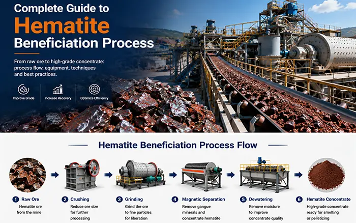
The complete guide to hematite beneficiation explains why mineralogy and liberation size should determine the separation route.
7. Treat Water Consumption as Part of the Energy Balance
The two high-gradient magnetic separation stages require substantial process-water flow. This water must be supplied, clarified, circulated and pumped, which connects the plant’s water balance directly to its energy balance.
The plant design includes:
One 50 m concentrate thickener
One 38 m tailings thickener
Return-water pumps rated at 1,450 m³/h
Return-water pump head of 43 m
Scheduled return-water pumping load of 250 kW
Improving thickener overflow clarity and maximizing safe water reuse can reduce fresh-water consumption. However, circulating water at a higher pressure than the plant requires increases pumping energy.
Flow meters should be installed on the main process-water branches, especially those supplying the high-gradient magnetic separators and filtration systems.
Pressure gauges should also be installed at critical users. A control valve that remains heavily throttled during normal production may indicate that the pump duty point or water distribution pressure should be reviewed.
Water performance should be reported in cubic metres per tonne of ore, together with the electricity required by the return-water system.
8. Optimize Dewatering for the Required Moisture
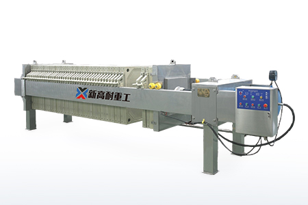
Concentrate dewatering uses six ZPG-120 disc filters. The equipment schedule shows an operating load of 372 kW for the filtration configuration, including the associated vacuum system.
Tailings dewatering uses three 500 m² filter presses with a scheduled operating load of 15 kW. The variable-frequency filter-press feed pumps add another 90 kW.
Dewatering energy should be evaluated per tonne of dry solids and compared with the required final moisture.
Attempting to produce a cake that is drier than required for transportation, storage or downstream use may increase electricity consumption and reduce filtration capacity without creating additional value.
For the concentrate disc filters, operators should monitor:
Feed pulp density
Vacuum level
Filter-sector condition
Filtrate clarity
Cake thickness
Cake moisture
Blowback pressure and timing
For the tailings filter presses, operators should monitor:
Feed pressure
Filling time
Complete cycle time
Filter-cloth condition
Filtrate clarity
Cake moisture
Dry solids processed per cycle
Feed-pump speed
The correct operating endpoint is not necessarily the driest possible filter cake. It is the lowest total operating cost that still produces a manageable cake and reusable process water.
9. Conduct a Controlled Plant Trial
A specific energy-saving percentage cannot be calculated from equipment power alone. A stable baseline must be established before making performance claims.
A practical plant trial can follow this sequence:
Operate the plant under stable ore and throughput conditions for several representative shifts.
Record synchronized power, tonnage, particle size, pulp density, grade, recovery and product-moisture data.
Change one controllable group of parameters, such as cyclone pressure or grinding-media grading.
Allow the circulating load and downstream process to reach a new steady state.
Repeat the sampling and compare equivalent operating periods.
Retain the change only if it reduces energy without causing an unacceptable change in throughput, grade, recovery, wear or water consumption.
The plant should report at least four main performance indicators:
kWh per tonne of feed
kWh per tonne of concentrate
Concentrate Fe grade
Iron recovery
Equipment availability, grinding-media consumption, liner wear, process-water consumption and product moisture should also be included in the economic evaluation.
10. Recommended Optimization Priorities for This 200 TPH Plant
| Priority | Recommended action | Reason | Verification metric |
|---|---|---|---|
| 1 | Meter the two grinding stages separately | Grinding represents approximately 63.9% of scheduled power | kWh/t for each grinding stage |
| 2 | Audit cyclone separation and circulating load | Misclassification returns finished fines to the mills | Overflow size and fines in underflow |
| 3 | Stabilize variable-speed cyclone feed pumps | Pump operation affects direct power and grinding efficiency | Pressure variation and pump kWh/t |
| 4 | Optimize the ball charge and inspect liners | Media and liners determine how motor power is transferred to the ore | Throughput at an equivalent product size |
| 5 | Optimize high-gradient magnetic separation | Better selectivity may reduce unnecessary regrinding | Grade and recovery by particle-size fraction |
| 6 | Balance process water and return water | The magnetic circuit has high water demand | m³/t and return-water pump kWh/t |
| 7 | Optimize filtration endpoints | Excessive drying increases energy and lowers capacity | kWh/t dry solids and cake moisture |
11. What Data Is Needed Before Quoting an Energy-Saving Percentage?
The supplied design data are sufficient to identify the most important optimization areas, but they are not sufficient to promise a specific percentage reduction.
A defensible before-and-after calculation still requires:
Electricity-meter data for each major process area
Actual dry throughput
Actual operating hours
Feed and product moisture
Mill feed-size distribution
Cyclone overflow P80
Cyclone pressure and feed density
Circulating load
Actual duty and standby equipment schedule
Feed-grade variation
Ore hardness or grinding test data
Concentrate grade during each trial
Iron recovery during each trial
Trial duration and repeatability
Once these data are available, the design analysis can be developed into a genuine operating case study with verified energy and metallurgical results.
Ask a XINGAONAI Engineer to Review Your Hematite Plant
The power distribution and optimization priorities described in this article are specific to the supplied 200 TPH design.
Your plant may require a different grinding arrangement, magnetic field intensity or dewatering system because mineral composition, liberation size, ore hardness, feed moisture and production targets vary between deposits.
If you are planning a new hematite processing plant or trying to reduce the energy consumption of an existing line, contact a XINGAONAI mineral processing engineer.
To receive a more useful preliminary assessment, provide as much of the following information as possible:
Mineral analysis or beneficiation test report
Required feed capacity
Operating hours per day
Feed Fe grade
Target concentrate grade
Required iron recovery
Maximum feed size
Target grinding size
Existing equipment models
Installed motor powers
Measured electricity consumption
Existing process flowsheet
Equipment layout
Site photographs or operating videos
Based on these inputs, the XINGAONAI engineering team can help determine whether the priority should be grinding and classification control, magnetic separation optimization, variable-frequency pumping, dewatering improvement or a broader flowsheet adjustment.
Customers can submit project information through the XINGAONAI contact page or call +86 17335795666 to discuss their material and production requirements.
Conclusion
In this 200 TPH hematite processing plant design, two-stage ball milling is the dominant electrical load. The two grinding stages account for approximately 3,450 kW, or 63.9% of the listed operating total.
Grinding and slurry-water pumping together account for approximately 78.5% of the scheduled load. Stable feeding, accurate cyclone classification, appropriate grinding-media sizing and efficient pump control should therefore be the first optimization priorities.
The theoretical value of 26.99 kWh per tonne of feed is a useful design benchmark, not measured plant consumption. Actual energy savings must be calculated from synchronized electricity, throughput and metallurgical data.
The objective is to reduce energy per tonne while maintaining the required concentrate grade and iron recovery—not merely to lower instantaneous power draw.
For equipment selection, process design or an energy-efficiency review, send your ore and operating information to the XINGAONAI engineering team. More complete feed, product and power data will allow the engineers to provide a more specific technical recommendation.