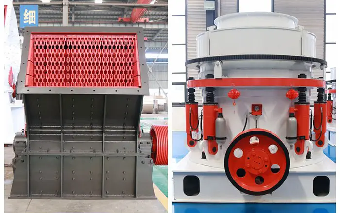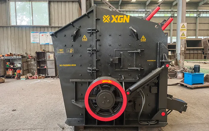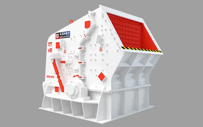
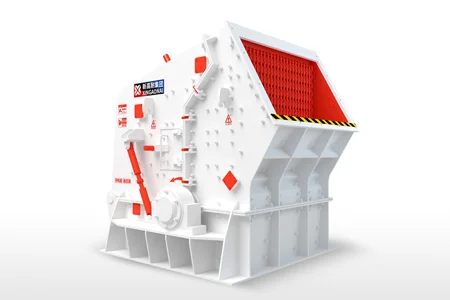
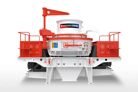
Impact crusher maintenance should prevent predictable wear from developing into an unexpected shutdown. A reliable program combines operating inspections, wear measurements, lubrication control, planned replacement and accurate maintenance records.
An impact crusher operates with a high-speed rotor, repeated impact loads and continuous material movement through the crushing chamber. Blow bars, impact plates and liners gradually wear, while bearings, shafts, locking components, belts, hydraulic systems and structural connections must remain properly aligned and secured.
Maintenance should therefore follow a continuous process:
Inspect → Measure → Record → Compare → Plan → Maintain
Waiting until a component fails can turn a short, planned replacement into damage involving the rotor, bearings, shaft or crusher frame.
This guide provides:
A daily impact crusher maintenance checklist.
Weekly and periodic inspection tasks.
Planned-shutdown procedures.
Maintenance requirements for blow bars, rotor, bearings and aprons.
Lubrication and hydraulic-system checks.
Common fault diagnosis.
Wear-recording and spare-parts planning guidance.
The procedures primarily apply to horizontal-shaft impact crushers, including XINGAONAI PF-series machines. Exact limits, lubricant specifications, tightening torques and replacement criteria must always come from the manual for the specific crusher model.
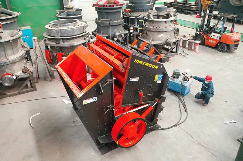
Why Impact Crusher Maintenance Matters
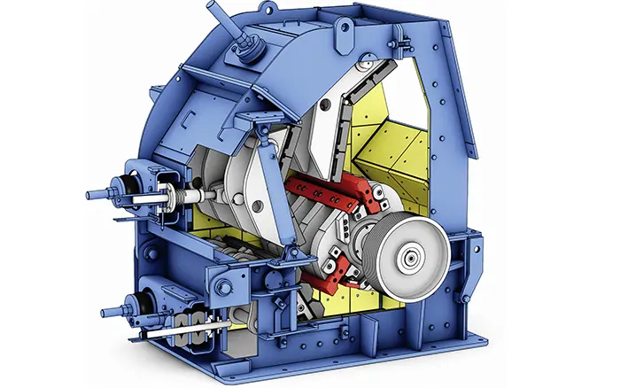
A horizontal-shaft impact crusher reduces material through high-speed impacts between the blow bars, material particles and impact aprons.
This operating principle can produce a high reduction ratio and well-shaped aggregate, but it also creates demanding conditions inside the crusher:
Repeated impact loading.
Abrasive material flow.
High rotor speed.
Dust and contamination.
Vibration.
Changing feed conditions.
Heat around bearings and drive components.
A planned maintenance program helps:
Reduce unplanned downtime.
Maintain stable production capacity.
Control finished-product size and shape.
Extend the service life of wear parts.
Protect the rotor, shaft and bearings.
Reduce secondary damage.
Improve maintenance safety.
Prepare replacement parts before they are needed.
Lower the total processing cost per tonne.
Maintenance does not eliminate normal wear. Its purpose is to keep wear measurable, predictable and controlled.
Understand Normal Operating Conditions First
Operators cannot identify an abnormal condition unless they understand how the crusher behaves during normal operation.
Create a baseline for:
Normal operating sound.
Vibration level and pattern.
Bearing temperature.
Motor current.
Rotor speed.
Feed rate.
Hydraulic pressure.
Product gradation.
Crusher throughput.
Recirculating load.
Dust and leakage condition.
A single reading may provide limited information. A trend across several shifts is usually more valuable.
For example, a bearing temperature that remains stable may be normal for that machine. A lower temperature that rises continuously from one shift to the next may require investigation.
Operators should record significant changes instead of relying on memory.
Impact Crusher Maintenance Schedule at a Glance
| Maintenance stage | Main purpose | Typical checks |
|---|---|---|
| Before startup | Confirm that the machine is ready for safe operation | Guards, chamber condition, fasteners, lubrication, belts, hydraulic leaks and clearances |
| During operation | Detect changes before damage develops | Noise, vibration, temperature, motor load, feed distribution and product condition |
| After shutdown | Identify visible wear and prepare corrective work | Blow bars, aprons, liners, buildup, loose fasteners and leakage |
| Weekly inspection | Examine developing problems more closely | Wear measurements, belt condition, locking parts, structural joints and lubrication lines |
| Periodic inspection | Review components that require measurement or testing | Rotor condition, bearing system, hydraulic system, alignment and safety devices |
| Planned shutdown | Complete internal inspection and major service | Wear-part replacement, rotor inspection, bearing service and structural inspection |
| Annual or major service | Assess the complete machine | Rotor and shaft, bearings, frame, drive, hydraulic system and electrical controls |
These intervals are planning categories, not universal replacement limits. Actual frequency must reflect:
Crusher model.
Operating hours.
Feed material.
Abrasiveness.
Feed size.
Moisture.
Production rate.
Site environment.
Previous inspection results.
Manufacturer requirements.
Safety Before Inspection or Maintenance
Impact crushers contain stored mechanical, electrical, hydraulic and gravitational energy. Internal inspection must only begin after the crusher has been stopped, isolated and secured according to the site’s approved procedure.
Before entering or working around the crushing chamber:
Stop feeding material.
Allow the crusher and downstream equipment to clear.
Shut down the crusher according to the correct sequence.
Isolate all energy sources.
Apply the site’s lockout and tagout procedure.
Verify that the rotor has stopped completely.
Release stored hydraulic or pneumatic pressure where required.
Mechanically support raised covers or crusher sections.
Confirm that no material can fall into the chamber.
Use approved lifting equipment for heavy wear parts.
Maintain communication between operations and maintenance personnel.
Inspect tools and lifting accessories before use.
Never rely only on the hydraulic system to support an opened crusher housing. Use the mechanical support or locking device specified for the machine.
Do not attempt to remove blocked material while the rotor can move or while upstream equipment can feed the crusher.
Daily Impact Crusher Maintenance Checklist
Daily maintenance should be divided into three stages:
Before Startup → During Operation → After Shutdown
1. Before-Startup Inspection
Check the Previous Shift’s Records
Review:
Abnormal noise or vibration.
High-temperature events.
Lubrication warnings.
Changes in motor current.
Reduced capacity.
Product-size changes.
Pending repairs.
Parts approaching their wear limit.
This prevents an unresolved problem from being overlooked during the next startup.
Inspect the Feed and Crushing Chamber
When safe access is available, check for:
Material remaining inside the chamber.
Tramp metal or other uncrushable objects.
Oversized feed.
Excessive wet or sticky buildup.
Loose wear parts.
Visible cracks.
Obstructions around the discharge.
The rotor must be able to rotate without interference. Do not start the machine when a foreign object, loose component or large accumulation is present inside the chamber.
Inspect Blow Bars and Locking Components
Check the visible condition of:
Blow bars.
Wedges.
Locking blocks.
Pins.
Bolts.
Retaining plates.
Blow-bar seating surfaces.
Look for:
Cracks.
Chipped edges.
Uneven wear.
Movement inside the rotor.
Loose locking components.
Missing fasteners.
Material packed behind a blow bar.
A significant difference in profile between bars.
The blow bars are the main impact components. Their condition affects rotor balance, crushing energy and product size.
For component names, materials and replacement considerations, refer to the impact crusher parts guide.
Check the Impact Aprons and Liners
Inspect:
Impact plates.
Apron liners.
Side liners.
Feed-chute liners.
Discharge protection.
Liner bolts.
Confirm that:
No plate is broken.
No liner has moved from its installed position.
Fasteners are present.
Wear has not exposed the supporting structure.
The apron adjustment is secure.
Material has not accumulated behind loose liners.
Check Lubrication Condition
Verify:
Lubricant level, where applicable.
Grease or oil delivery.
Leakage.
Damaged hoses or pipes.
Loose fittings.
Contamination.
Previous high-temperature warnings.
Do not add lubricant simply because a bearing has operated at a high temperature. Overlubrication, contamination, bearing damage, misalignment and excessive load can also cause heat.
Use the lubricant type, quantity and service interval specified for the exact crusher and bearing arrangement.
Check the Drive System
Inspect:
Belt condition.
Belt tension.
Pulley alignment.
Belt guards.
Motor mounting bolts.
Pulley fasteners.
Coupling condition, where fitted.
Dust or oil contamination on the belts.
Do not operate the crusher without the drive guards installed.
Check the Hydraulic System
Look for:
Oil leakage.
Damaged hoses.
Loose connections.
Cylinder damage.
Abnormal pressure readings.
Unsupported raised components.
Contaminated hydraulic oil.
Check Safety Devices
Confirm the condition of:
Emergency stops.
Safety switches.
Interlocks.
Guards.
Access-door locks.
Warning devices.
Temperature and vibration alarms.
Communication devices.
A damaged or bypassed safety device should be corrected before operation.
2. Checks During Operation
Observe Feeding Conditions
The crusher should receive a controlled and reasonably distributed feed.
Watch for:
Material entering mainly on one side.
Sudden surges.
Long periods of underfeeding.
Oversized material.
Excessive fines.
Wet or sticky material.
Tramp metal.
Feed-chute buildup.
Uneven feeding can produce uneven blow-bar and liner wear. Surges can overload the rotor, motor and drive system.
Monitor Noise and Vibration
Become familiar with the crusher’s normal sound and vibration.
Investigate:
Sudden knocking.
Repeated metallic impact.
Scraping.
Rattling.
Increasing vibration.
Movement of the crusher or supports.
Changes after wear-part replacement.
If vibration increases sharply, stop the crusher according to the approved procedure. Possible causes include a loose blow bar, rotor imbalance, uneven wear, material buildup, bearing damage or structural loosening.
Monitor Bearings
Track:
Bearing temperature.
Temperature trend.
Lubrication pressure or flow, where monitored.
Noise.
Vibration.
Leakage.
A continuously rising temperature requires investigation even if the alarm limit has not yet been reached.
Compare both bearing positions. A large difference can help identify a local lubrication, loading, alignment or bearing problem.
Monitor Motor Load
Motor current can reveal:
Overfeeding.
Material buildup.
An obstructed discharge.
Changes in material hardness.
Incorrect apron setting.
Drive slippage.
Mechanical resistance.
Do not increase the feed rate solely to compensate for lower capacity. First determine whether wear, blockage, screen performance or another condition has changed.
Observe the Finished Product
Changes in the crushed product can indicate a maintenance issue.
Check for:
Increasing top size.
More oversize material.
Excessive fines.
Poor particle shape.
Unstable gradation.
Reduced output.
Possible causes include worn blow bars, worn impact plates, an altered apron gap, changing rotor speed, unstable feeding or poor downstream screening.
Understanding how an impact crusher works makes it easier to connect changes in product quality with the rotor, blow bars and impact aprons.
3. After-Shutdown Inspection
After safe isolation:
Remove material buildup from accessible areas.
Inspect blow-bar wear.
Check the apron liners.
Inspect side liners.
Look for loose fasteners.
Check for oil or grease leakage.
Inspect belt condition.
Check feed and discharge areas.
Record damage or abnormal wear.
Prepare parts and tools for the next planned shutdown.
Cleaning should not remove information that maintenance personnel need for diagnosis. Before removing unusual buildup, photograph its location and record the condition.
【Image Position 3: After the daily maintenance section】
Suggested image: Blow-bar profile being measured during a shutdown inspection.
Suggested filename: impact-crusher-blow-bar-inspection.jpg
Suggested ALT text: Measuring blow bar wear during impact crusher maintenance
Weekly Inspection Checklist
Weekly checks should provide a closer examination of conditions observed during daily inspections.
Wear-Part Measurement
Measure and record:
Blow-bar profile.
Minimum remaining section.
Wear at both ends.
Impact-plate thickness.
Side-liner thickness.
Wear around bolt holes.
Condition of rotor-protection parts.
Use consistent measuring points. A measurement taken from a different position each week cannot produce a reliable trend.
Photographs should be taken from similar angles and labelled with:
Date.
Crusher model.
Operating hours.
Part position.
Material processed.
Measurement result.
Blow-Bar Weight and Position
When bars are removed or replaced:
Identify their installed positions.
Confirm that replacement bars are compatible.
Compare their weights.
Inspect the seating surfaces.
Check wedges and locking components.
Clean the contact areas.
Follow the specified installation sequence.
Installing bars with an unacceptable difference in mass can create rotor imbalance.
Check Bolts and Structural Connections
Inspect:
Bearing-housing bolts.
Motor-base bolts.
Apron and liner fasteners.
Frame connections.
Access-door hardware.
Foundation or anchor bolts.
Hydraulic-cylinder mountings.
Use the specified tightening procedure and torque. Do not apply a universal torque value to different grades and sizes of fastener.
Inspect the Belt Drive
Check:
Belt tension.
Pulley alignment.
Groove wear.
Belt cracking.
Glazing.
Fraying.
Dust contamination.
Evidence of slippage.
If multiple belts form one drive set, replace them according to the drive manufacturer’s requirements. Mixing heavily worn and new belts can distribute the load unevenly.
Inspect Lubrication Lines and Seals
Check for:
Cracked hoses.
Blocked lines.
Loose fittings.
Damaged seals.
Contaminated lubricant.
Excess grease discharge.
Evidence of water or dust entry.
Periodic Inspection
The periodic interval should be based on operating hours, material abrasiveness and previous inspection results rather than an arbitrary calendar date.
Rotor Inspection
Inspect the rotor for:
Cracks around blow-bar seats.
Deformed slots.
Worn contact surfaces.
Damage around locking components.
Missing protection plates.
Material accumulation.
Signs of movement between parts.
Damage near the shaft connection.
Previous repair areas.
A damaged seating surface can prevent a new blow bar from being held correctly. Installing a new bar without repairing the underlying seat may cause repeat loosening.
Rotor Balance
Rotor balance should be evaluated after:
Replacing blow bars.
Repairing the rotor.
Welding rotor components.
Replacing rotor-protection parts.
Removing heavy material buildup.
Experiencing unexplained vibration.
Do not continue operating with persistent vibration after a wear-part change.
Shaft Inspection
Check:
Bearing seats.
Keyways.
Threads.
Shaft shoulders.
Coupling or pulley mounting areas.
Transition radii.
Signs of movement.
Corrosion.
Cracks.
Bending or runout.
A suspected cracked or bent shaft requires a proper engineering inspection before the crusher returns to service.
Bearing Inspection
Evaluate:
Temperature history.
Vibration trend.
Noise.
Lubricant condition.
Internal or operating clearance where required.
Bearing-seat condition.
Housing condition.
Seal condition.
Alignment.
Replacing a bearing without finding the cause of failure may result in repeated damage. Inspect the shaft seat, housing, lubrication system, alignment and load condition at the same time.
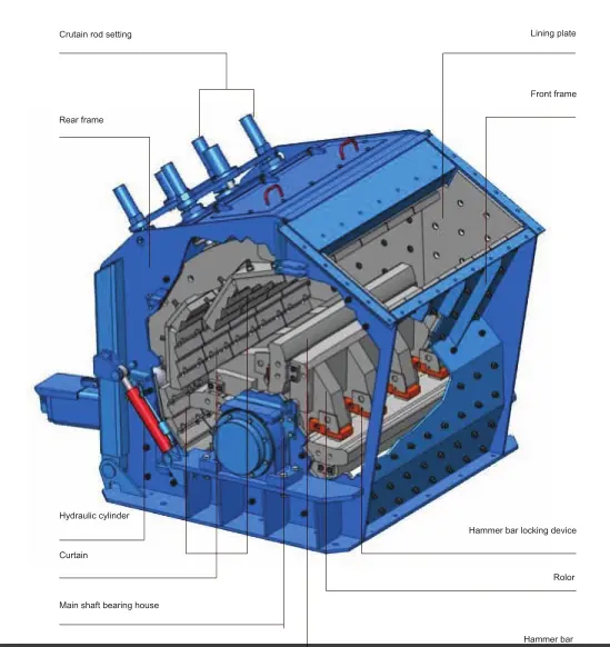
Impact Apron and Gap Inspection
The gap between the rotor and impact apron affects material movement and product size.
Check:
Apron position.
Adjustment mechanism.
Spring or hydraulic protection.
Liner thickness.
Liner alignment.
Pivot points.
Pins and bushes.
Structural cracks.
Material buildup behind the apron.
Record the setting method and measurement location. A gap measurement is only useful when it is taken consistently.
A smaller gap does not automatically provide better production. It can increase fines, recirculating load, energy demand and wear. The setting should support the required product and total circuit performance.
Frame and Housing Inspection
Check the structural components for:
Cracks near welds.
Cracks around bearing supports.
Deformation.
Loose structural bolts.
Damaged access doors.
Worn hinges or locking devices.
Damaged mounting surfaces.
Material leakage.
Contact between moving and stationary parts.
Signs of foundation movement.
Do not cover a structural crack with a quick weld before determining why it formed. Location, direction, depth, loading and material must be assessed before selecting a repair procedure.
Hydraulic-System Inspection
Inspect:
Oil level and condition.
Filters.
Pump.
Valves.
Cylinders.
Rod surfaces.
Seals.
Hoses.
Fittings.
Accumulators, where installed.
Pressure readings.
Mechanical support devices.
Investigate:
Repeated pressure loss.
Slow movement.
Uneven movement.
Cylinder drift.
Leakage.
Abnormal noise.
Contaminated oil.
Hydraulic oil cleanliness is important because contaminated fluid can damage valves, pumps and cylinder seals.
Electrical and Control-System Inspection
Inspect:
Motor terminals.
Cables.
Control cabinets.
Sensors.
Temperature probes.
Vibration monitors.
Interlocks.
Emergency stops.
Alarm history.
Evidence of overheating or moisture entry.
Electrical inspection and repair should be performed by qualified personnel.
Lubrication Management
Lubrication is more than adding grease or oil. An effective program controls:
Correct lubricant type.
Correct quantity.
Correct delivery method.
Service interval.
Contamination.
Storage.
Sampling or condition checks.
Disposal and replacement records.
Common Lubrication Mistakes
Avoid:
Mixing incompatible lubricants.
Adding excessive grease.
Using a generic lubricant without confirming suitability.
Ignoring leaking seals.
Leaving lubricant containers open.
Using dirty transfer equipment.
Assuming that visible lubricant means the bearing is properly lubricated.
Changing the lubricant without investigating contamination.
What a High Bearing Temperature May Mean
Possible causes include:
Too little lubricant.
Too much lubricant.
Incorrect viscosity or grease consistency.
Contaminated lubricant.
Blocked lubrication line.
Damaged bearing.
Incorrect bearing clearance.
Misalignment.
Excessive rotor load.
Belt tension that is too high.
High ambient temperature.
Sensor or measurement error.
The cause should be diagnosed before adding more lubricant.
Blow-Bar and Wear-Part Maintenance
Blow-bar life depends on:
Material hardness.
Abrasiveness.
Silica content.
Feed size.
Feed distribution.
Moisture.
Rotor speed.
Chamber setting.
Blow-bar material.
Tramp-metal control.
Operating practices.
There is no universal replacement interval.
Replace or Rotate Blow Bars?
Some blow-bar designs can be turned to use another working face. Before rotating a bar, confirm:
The design permits rotation.
The remaining section is above the specified limit.
The bar has no cracks.
The locking surfaces are intact.
The new working position will not interfere with the chamber.
All bars remain compatible in mass and material.
The manufacturer’s procedure is followed.
Do not rotate a cracked or deformed bar.
Replace Blow Bars When
Replacement should be planned when:
The manufacturer’s wear limit is reached.
The bar can no longer be secured correctly.
Cracks or severe chipping are present.
Uneven wear threatens rotor balance.
Product size cannot be maintained.
Crushing efficiency decreases.
Continued operation could expose or damage the rotor.
The next planned shutdown would occur after the safe remaining service life.
Inspect Adjacent Components During Replacement
Whenever blow bars are removed, inspect:
Rotor slots.
Seating surfaces.
Wedges.
Locking blocks.
Pins.
Bolts.
Rotor-protection plates.
Apron liners.
Side liners.
Material buildup.
A new blow bar cannot correct a damaged rotor seat or worn locking system.
Planned-Shutdown Maintenance
Planned shutdowns provide access to components that cannot be safely inspected during normal operation.
Prepare Before the Shutdown
Before stopping production:
Review inspection records.
Define the work scope.
Confirm replacement parts.
Check part numbers and dimensions.
Prepare lifting equipment.
Prepare tools and measuring equipment.
Assign responsibilities.
Confirm isolation points.
Estimate the work sequence.
Prepare contingency parts.
Coordinate maintenance with upstream and downstream equipment.
A well-prepared shutdown should not begin with technicians searching for parts or discovering that the lifting equipment is unsuitable.
Internal Crusher Inspection
After isolation and safe access:
Clean enough material to expose the inspection areas.
Photograph the initial condition.
Measure blow bars and liners.
Inspect locking components.
Examine the rotor.
Inspect aprons and adjustment mechanisms.
Check side liners.
Inspect the feed and discharge zones.
Check the frame and doors.
Record all findings.
After Reassembly
Before startup:
Confirm that all tools and loose items have been removed.
Check the installation of blow bars and locks.
Verify fasteners.
Confirm apron settings.
Check the rotor’s free movement according to the approved procedure.
Restore guards.
Restore lubrication and hydraulic systems.
Remove maintenance locks only according to the site procedure.
Conduct the specified no-load or commissioning checks.
Monitor vibration, temperature and noise during restart.
Common Problems and Troubleshooting
| Problem | Possible causes | Recommended checks |
|---|---|---|
| Excessive vibration | Uneven blow-bar wear, different bar weights, loose parts, rotor buildup, bearing damage or structural loosening | Stop safely, inspect bars and locks, clean the rotor, check bearings and structural fasteners |
| Repeated metallic knocking | Loose blow bar, broken liner, foreign metal or contact between components | Stop feeding, isolate the crusher and inspect the chamber |
| Product becoming coarser | Worn bars or impact plates, changed apron gap, reduced rotor speed or unstable feeding | Measure wear, verify settings, inspect the drive and check the feed |
| Excessive fines | Gap too small, rotor speed too high, excessive recirculation or unsuitable feed | Review settings, rotor speed, screening and feed characteristics |
| Reduced capacity | Worn parts, material buildup, blocked discharge, uneven feeding, belt slip or downstream restriction | Inspect the complete material path rather than only the crusher |
| High bearing temperature | Lubrication problem, contamination, misalignment, excessive belt tension, overload or bearing damage | Review the temperature trend and inspect lubrication, alignment, drive and bearing condition |
| Blow bar wears faster on one end | Feed concentrated on one side or uneven chamber flow | Inspect the chute, feeder, material distribution and apron alignment |
| One bar wears faster than the others | Different material or weight, installation issue, damaged seat or uneven feed | Compare all bars and inspect rotor seating surfaces |
| Liner bolts repeatedly loosen | Damaged mounting surface, incorrect fastener, wrong torque or excessive vibration | Inspect the support surface, bolt grade, tightening procedure and vibration source |
| Hydraulic system loses pressure | Leakage, damaged seals, faulty valve, hose damage or pump wear | Inspect the complete hydraulic circuit |
| Motor current is unstable | Irregular feeding, changing material, blockage or mechanical resistance | Check the feed system, chamber, discharge and drive |
| Product shape deteriorates | Worn blow bars, worn aprons, unstable feed or unsuitable operating settings | Inspect wear condition and review crusher settings |
The same symptom can have several causes. Troubleshooting should combine visual inspection, operating data and maintenance history instead of replacing the first component suspected.
Use Wear Records to Predict Replacement
A useful maintenance record should include more than “normal” or “worn.”
Record:
Date.
Operating hours.
Material type.
Feed size.
Production rate.
Blow-bar measurements.
Liner measurements.
Apron setting.
Bearing temperatures.
Vibration readings.
Motor current.
Lubrication work.
Parts replaced.
Photographs.
Abnormal events.
Corrective actions.
The progression may look like:
Inspection 1: Normal profile
Inspection 2: Measurable wear
Inspection 3: Accelerated wear
Inspection 4: Replacement planned
When a part shows a repeatable wear rate under similar conditions, the next inspection and replacement can be scheduled more accurately.
Sudden changes in wear rate should trigger an investigation into:
Feed material.
Feed distribution.
Throughput.
Rotor speed.
Apron setting.
Tramp-metal events.
Replacement-part material.
Operating practices.
Coordinate Crusher Maintenance with the Entire Plant
An impact crusher does not operate independently.
The material path may include:
Feeder → Primary Crusher → Impact Crusher → Vibrating Screen → Conveyor
A problem in another machine can affect the crusher:
An unstable feeder creates changing rotor load.
Poor primary crushing sends oversized material.
A damaged screen increases recirculation.
A restricted conveyor obstructs discharge.
Tramp metal can damage blow bars and the rotor.
Coordinate crusher work with the broader aggregate equipment maintenance schedule.
During one planned shutdown, the plant may complete:
Blow-bar and liner inspection.
Screen-media inspection.
Conveyor alignment.
Feeder inspection.
Lubrication service.
Bolt checks.
Magnet or metal-detector inspection.
Combining compatible work reduces repeated production interruptions.
Spare-Parts Planning
Frequently Used Wear Parts
Depending on the operating history, consider stocking:
A complete matched set of blow bars.
Impact-plate liners.
Apron liners.
Side liners.
Rotor-protection plates.
Feed and discharge liners.
Wedges and locking blocks.
Model-specific fasteners.
Critical Service Parts
Consider availability and delivery time for:
Bearings.
Seals.
Belts.
Hydraulic hoses.
Sensors.
Lubrication components.
Cylinder-seal kits.
Special fasteners.
Major Components
A spare rotor or shaft may not be necessary at every plant, but management should know:
Manufacturing lead time.
Repair options.
Lifting requirements.
Installation time.
Transport time.
Cost of extended downtime.
If a major component is damaged, compare its condition, repair risk and required service life. The crusher component rebuild vs replacement guide provides a framework for evaluating the two options.
Common Maintenance Mistakes
Avoid the following practices:
Waiting until a wear part breaks.
Using fixed replacement hours without measuring wear.
Adding lubricant whenever a bearing becomes hot.
Mixing incompatible lubricants.
Installing blow bars with unverified weight differences.
Replacing bars without inspecting wedges and rotor seats.
Ignoring uneven wear.
Adjusting the apron gap without recording the setting.
Reusing critical fasteners without inspection.
Welding the rotor without an approved procedure.
Restarting after a repair without monitoring vibration.
Focusing only on the crusher while ignoring feeding and screening.
Keeping no maintenance or replacement records.
Ordering parts only by their general name.
Working beneath a hydraulically raised section without mechanical support.
Maintenance of XINGAONAI PF Impact Crushers
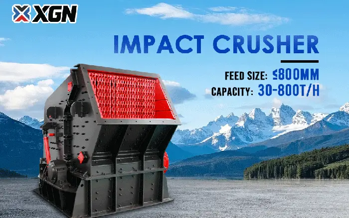
XINGAONAI PF impact crushers include models from PF1007 to PF1820. According to the current XINGAONAI impact crusher specifications, available capacities range from approximately 30 to 800 t/h, with maximum feed sizes from approximately 300 to 800 mm depending on the model.
Maintenance requirements differ between models because they may use different:
Rotor dimensions.
Blow-bar profiles.
Bearing arrangements.
Motor powers.
Belt configurations.
Impact aprons.
Hydraulic components.
Fastener sizes.
When requesting maintenance support or replacement parts, provide:
Crusher model.
Serial number.
Part name.
Part number.
Drawing or dimensions.
Photographs.
Material being processed.
Feed size.
Required product size.
Capacity.
Operating hours.
Description of the problem.
Recent maintenance records.
Conclusion
Effective impact crusher maintenance is not based on a single inspection or a universal replacement interval. It is a continuous system built around observation, measurement, recording and planned action.
A reliable maintenance program should:
Establish normal operating baselines.
Inspect the crusher before, during and after each shift.
Measure wear at consistent locations.
Monitor vibration, temperature and motor load.
Maintain model-specific lubrication requirements.
Inspect blow-bar locking components during every replacement.
Protect rotor balance.
Coordinate maintenance with the complete crushing circuit.
Keep critical replacement parts available.
Investigate the cause of failure before installing a new component.
Use planned shutdowns for internal and structural inspection.
The objective is not to operate every part for the maximum possible number of hours. It is to replace or repair each component at the point that provides safe operation, stable production and the lowest overall cost per tonne.