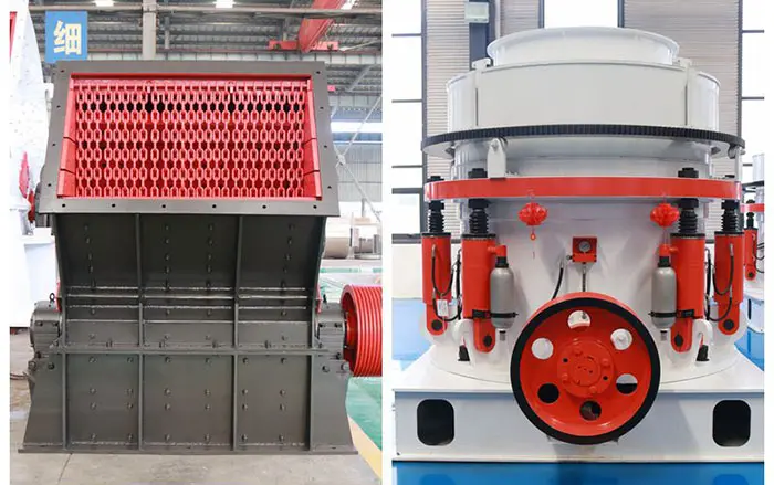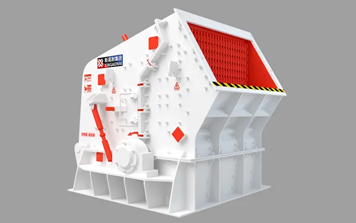
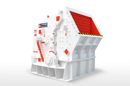
Impact crusher parts directly affect crushing performance, product shape, operating stability and cost per tonne. The principal components include the rotor, blow bars, impact aprons, breaker plates, side liners, bearings, shaft, drive system, frame and hydraulic adjustment system.
Some components are designed to wear and be replaced. Others are structural or mechanical assemblies that should be inspected, measured and repaired only after their condition has been properly evaluated.
Understanding the function of each part helps operators:
Identify abnormal wear before it causes secondary damage
Maintain consistent product gradation
Reduce unplanned shutdowns
Order compatible replacement parts
Select suitable wear-part materials
Decide whether a component should be replaced or assessed for rebuilding
This guide focuses on horizontal-shaft impact crushers, including the XINGAONAI PF Series impact crusher. Vertical-shaft impact crushers use a different rotor and wear-part arrangement.

Main Impact Crusher Parts at a Glance
| Part | Main function | Component category | Typical condition concern |
|---|---|---|---|
| Blow bars | Strike and accelerate the feed material | Wear part | Profile loss, cracks, uneven wear |
| Rotor body | Carries the blow bars and transfers impact energy | Major mechanical component | Cracks, deformation, damaged seats |
| Rotor shaft | Supports and drives the rotor assembly | Major mechanical component | Journal wear, bending, cracks |
| Impact aprons | Position the crushing surfaces opposite the rotor | Adjustable assembly | Distortion, damaged pivots or adjustment system |
| Breaker plates or apron liners | Provide the stationary impact surface | Wear part | Thinning, cracking, uneven wear |
| Side liners | Protect the sides of the crushing chamber | Wear part | Localized thinning and exposed frame |
| Bearings | Support high-speed rotor rotation | Service component | Heat, vibration, lubricant contamination |
| Bearing housings | Locate and protect the bearings | Mechanical component | Loose fit, seal damage, misalignment |
| Drive system | Transfers power from the motor to the rotor | Mechanical system | Belt wear, misalignment, loose connections |
| Hydraulic system | Opens the crusher and adjusts or protects the aprons | Service system | Leakage, pressure loss, damaged seals |
| Frame and housing | Support and align the crusher assemblies | Structural component | Cracks, deformation, loose fasteners |
| Feed and discharge protection | Guides material and protects exposed surfaces | Wear or structural component | Buildup, abrasion and deformation |
Part names vary among manufacturers. For example, “impact plate,” “breaker plate,” “apron liner” and “impact liner” may describe related but not always identical components. Always confirm the terminology used in the parts manual for the specific machine.
Wear Parts vs Spare Parts vs Major Components
These terms should not be treated as interchangeable.
Impact Crusher Wear Parts
Wear parts are components expected to lose material during normal operation. They usually include:
Blow bars
Breaker plates
Apron liners
Side liners
Feed-chute liners
Rotor protection plates
They are replaced after reaching the manufacturer’s wear limit, developing damage or no longer maintaining the required crushing performance.
Impact Crusher Spare Parts
Spare parts include wear parts as well as service and mechanical components kept to support maintenance. Examples include:
Bearings
Seals
Hydraulic hoses
Adjustment components
Fasteners
Belt sets
Locking wedges
Sensors
Not every spare part is a wear part.
Major Mechanical and Structural Components
The rotor body, rotor shaft, frame, bearing housings and apron assemblies are major components. These parts are not normally replaced according to a routine wear schedule.
Their condition should be evaluated through dimensional checks, alignment measurements, crack inspection and other procedures specified by the manufacturer.
1. Blow Bars
Blow bars are the primary crushing tools of a horizontal-shaft impact crusher. They are mounted in the rotor and strike the incoming material as the rotor turns.
The initial impact:
Fractures the feed
Accelerates the broken material
Directs particles toward the impact aprons
Creates further material-to-plate and material-to-material collisions
This process is explained in more detail in the guide to the impact crusher working principle.
Blow Bar Wear Signs
Common signs include:
Rounded or heavily worn working edges
Significant loss of the original profile
Uneven wear between bars
Chipping or cracking
Loose locking wedges
Reduced capacity
Coarser or less consistent product
Increased vibration after rotation or replacement
A worn working edge changes the point and direction of impact. This can reduce crushing efficiency even if the blow bar still contains usable metal.
Replacement decisions should be based on the manufacturer’s minimum dimensions, remaining usable profile and physical condition—not on operating hours alone.
Blow Bar Material Selection
| Material | General characteristics | Typical application considerations |
|---|---|---|
| High-chromium iron | Strong abrasion resistance but lower tolerance for severe impact | Clean, controlled and relatively low-impact feed |
| Martensitic steel | Balance between toughness and wear resistance | Mixed applications and selected recycling feed |
| Manganese steel | High impact tolerance and work-hardening behavior | Large feed or applications with significant impact loading |
| Ceramic-composite material | Increased wear resistance in suitable applications | Stable feed where the composite design matches the duty |
No material is best for every application.
Selection should consider:
Feed abrasiveness
Silica content
Maximum feed size
Presence of tramp metal
Required reduction
Rotor speed
Feed consistency
Moisture and clay
Product requirements
A highly wear-resistant material may be too brittle for severe impact or unpredictable recycling feed. Conversely, a tough material may provide insufficient abrasion resistance in a clean but highly abrasive application.
2. Rotor Assembly
The rotor assembly carries the blow bars and converts drive power into the kinetic energy required for crushing.
Depending on the design, it may include:
Rotor body
Rotor shaft
Blow-bar seats
Retaining wedges
Locking blocks
Rotor discs
Protective plates
Fasteners
The rotor is a major mechanical assembly, not a routine consumable.
Why Rotor Balance Matters
An impact crusher rotor operates at high speed. Uneven mass distribution can create centrifugal forces that increase with rotational speed.
Rotor imbalance may result from:
Blow bars with unequal weights
Uneven wear
Incorrect bar positioning
Missing or damaged locking components
Material buildup
Rotor repair without proper balancing
Localized damage to the rotor body
Possible symptoms include abnormal vibration, loosened fasteners, elevated bearing loads and damage to the shaft or frame.
Blow bars should therefore be installed in the specified positions and matched according to the manufacturer’s weight requirements.
Rotor Damage That Requires Assessment
Stop and evaluate the rotor if inspection identifies:
Cracks around blow-bar seats
Deformed or enlarged mounting areas
Damaged locking surfaces
Cracks in rotor discs or welded areas
Evidence of contact between rotating and stationary components
Abnormal shaft runout
Repeated loosening of blow-bar fasteners
Welding or machining a rotor without an approved repair procedure can change its strength, alignment and balance. Major repairs should include engineering evaluation and post-repair inspection.

3. Impact Aprons, Breaker Plates and Apron Liners
Impact aprons are adjustable assemblies positioned opposite the rotor. Their replaceable crushing surfaces may be called breaker plates, impact plates or apron liners.
The apron assembly and its liner should be distinguished:
The apron assembly supports and positions the crushing surface.
The liner or breaker plate is the replaceable surface exposed to material impact.
After the blow bars accelerate the material, particles strike the apron liners and fracture again. They may then return to the rotor path or collide with other particles.
How Apron Condition Affects Performance
Worn or damaged liners can cause:
Reduced crushing intensity
Coarser product
Unstable gradation
Higher recirculating load
Uneven material movement
Exposure of the supporting apron structure
The gap between the rotor and the aprons influences the crushing process, but it should not be treated as a precision product-size control on its own. Feed characteristics, rotor speed, wear condition and downstream screening also influence the final gradation.
What to Inspect
Inspect:
Remaining liner thickness
Wear distribution
Cracks and broken sections
Loose retaining bolts
Apron alignment
Pivot and support condition
Adjustment mechanism
Hydraulic cylinder and hose condition, where fitted
Replace the liner before the supporting apron structure becomes exposed to direct impact.
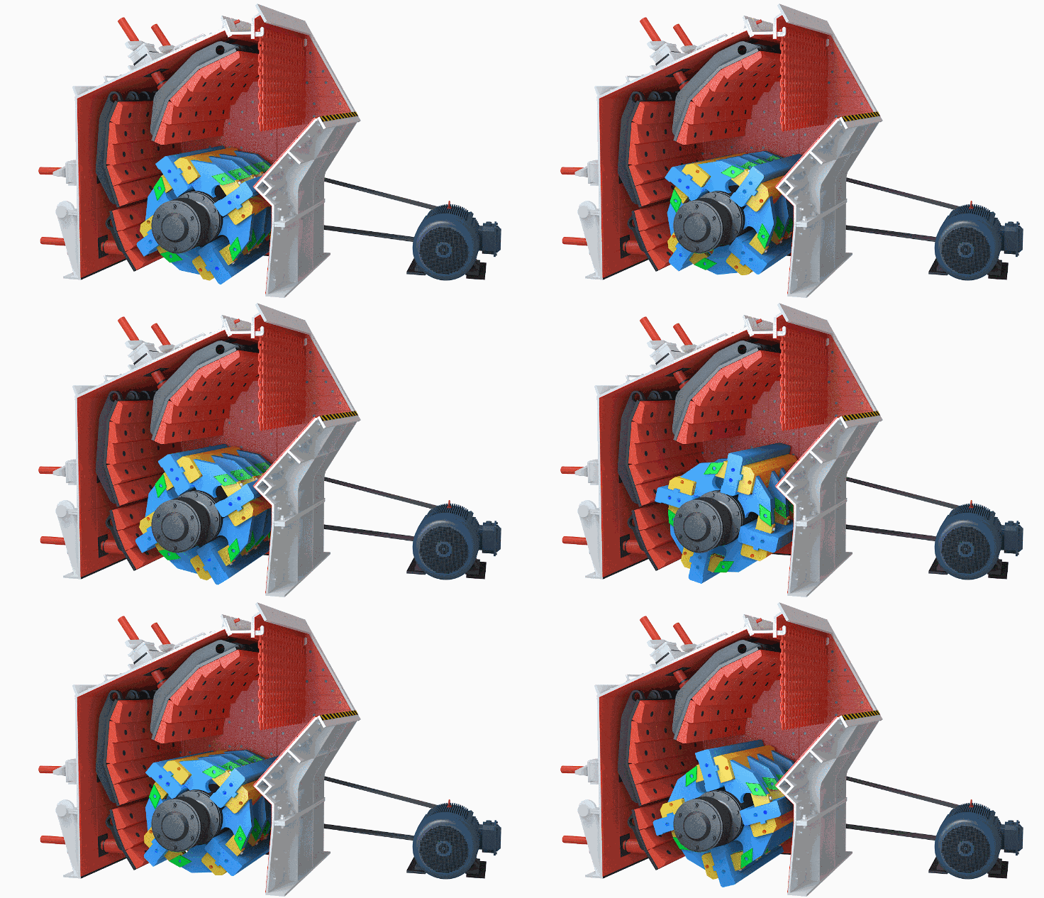
4. Side Liners and Chamber Protection
Side liners protect the internal walls of the crushing chamber from abrasion and repeated particle impact.
They may also be described as:
Side wear plates
Chamber liners
Frame liners
Protection plates
Side-liner wear is often uneven because material does not always spread uniformly across the full chamber width.
Localized wear may indicate:
Off-center feeding
Incorrect chute alignment
Uneven blow-bar wear
Material buildup
A feed distribution problem
A liner should not remain in operation after the supporting frame is exposed. Repairing structural wear is normally more expensive and time-consuming than replacing a liner during a planned shutdown.
When replacing side liners, check the condition of:
Mounting surfaces
Liner bolts
Countersunk holes
Backing material, where specified
Adjacent liners
Frame surfaces beneath the liners
5. Rotor Shaft
The rotor shaft supports the rotor and transmits torque from the drive system.
It is subjected to:
Torsional load
Bending load
Cyclic stress
Bearing reactions
Forces created by material impact
Additional forces caused by imbalance
Critical inspection areas include bearing journals, shoulders, keyways, transitions and other changes in section.
Signs that require further evaluation include:
Abnormal runout
Scoring or wear at bearing seats
Loose bearing fit
Cracks near shoulders or keyways
Heat discoloration
Fretting marks
Repeated seal failure
Persistent vibration after other causes have been eliminated
A shaft that appears visually acceptable may still require dimensional or nondestructive inspection. Do not continue operating a suspected cracked or bent rotor shaft.
6. Bearings, Housings and Seals
Rotor bearings support the rotating assembly and maintain shaft alignment. Depending on the crusher design, spherical roller bearings or another heavy-duty bearing arrangement may be used.
Bearing reliability depends on more than the bearing itself. The complete system includes:
Bearing
Housing
Shaft seat
Seals
Lubricant
Lubrication passage
Retaining components
Temperature or vibration sensors, where fitted
Common Bearing Warning Signs
Rising operating temperature
Abnormal noise
Increasing vibration
Lubricant leakage
Contaminated grease or oil
Metal particles in the lubricant
Loose housing fasteners
Damage around the seal
A hot bearing should not automatically be treated by adding more lubricant. Overlubrication, contamination, incorrect lubricant, excessive belt tension, misalignment and internal bearing damage can all produce heat.
Follow the model-specific lubrication specification and maintenance procedure.
7. Drive System Components
The drive system transfers motor power to the rotor. It may include:
Electric motor
V-belts
Pulleys
Coupling
Drive guard
Motor base
Tensioning system
Inspect the drive system for:
Uneven belt wear
Cracked or glazed belts
Incorrect belt tension
Misaligned pulleys
Loose motor-base fasteners
Damaged coupling elements
Contact between the guard and rotating parts
When multiple V-belts operate as a matched set, replacing only one stretched or damaged belt may create uneven load distribution. Follow the equipment or belt manufacturer’s replacement requirements.
8. Hydraulic Opening and Adjustment System
Many impact crushers use hydraulic components to open the housing, adjust apron position or provide overload movement.
The system may include:
Hydraulic cylinders
Pump
Reservoir
Hoses
Valves
Pressure gauges
Accumulators
Seals and fittings
Possible warning signs include:
Oil leakage
Loss of pressure
Apron position drifting
Slow or uneven movement
Damaged hoses
Contaminated fluid
Repeated pressure alarms
A hydraulic system must be depressurized and isolated before maintenance. Mechanical supports or locking devices specified by the manufacturer must be engaged before personnel enter or work beneath an opened crusher housing.
9. Frame, Housing and Access Doors
The frame maintains the alignment of the rotor, bearings and apron assemblies. Access doors or hydraulic opening sections provide entry for inspection and replacement work.
Inspect structural areas for:
Cracks
Deformation
Loose bolts
Damaged hinge or locking points
Worn mounting surfaces
Contact marks from internal components
Foundation movement
Evidence of material leakage
A crack in a noncritical cover and a crack near a bearing support do not carry the same risk. Structural damage around the rotor, bearing housing or main load path requires engineering assessment.
10. Fasteners and Blow-Bar Locking Components
Small components can cause major failures if they are ignored.
Critical items may include:
Blow-bar wedges
Locking blocks
Retaining pins
Liner bolts
Apron bolts
Bearing-housing bolts
Rotor fasteners
Hydraulic cylinder pins
Reuse is not automatically acceptable. Replace fasteners that are stretched, cracked, severely corroded, deformed or otherwise outside the manufacturer’s criteria.
Use the specified grade, dimensions and tightening procedure. A visually similar bolt with an incorrect grade can create a serious safety risk.
How Impact Crusher Parts Work Together
The crushing sequence can be summarized as follows:
Controlled Feed → Blow-Bar Impact → Acceleration → Apron Collision → Repeated Crushing → Discharge
Each component influences the next:
The feed system controls how material enters the rotor zone.
Blow bars deliver the initial impact.
The rotor determines the movement and energy of the blow bars.
Apron liners provide the stationary crushing surface.
Side liners contain and guide the material.
Bearings and the shaft support rotor movement.
The drive system supplies power.
The frame keeps the complete assembly aligned.
A problem with one component may therefore appear as a symptom somewhere else. For example, abnormal vibration may result from uneven blow-bar wear, material buildup, damaged bearings, a loose rotor component or drive misalignment.
Common Wear Patterns and What They May Indicate
| Observed condition | Possible contributing factors |
|---|---|
| One blow bar wears faster than the others | Uneven feed, unequal bar weight, incorrect positioning |
| One end of every blow bar wears faster | Feed concentrated on one side of the chamber |
| Blow bars chip or crack | Oversized feed, tramp metal, unsuitable material grade, incorrect installation |
| Apron liner wears unevenly | Misalignment, uneven material path, uneven blow-bar wear |
| Side liner has severe localized wear | Off-center feed or chute-distribution problem |
| Product gradually becomes coarser | Worn blow bars or aprons, changed setting or feed conditions |
| Vibration increases after replacement | Incorrect positioning, unmatched weights, loose locking parts |
| Bearing temperature rises | Lubrication problem, contamination, alignment issue, belt load or bearing damage |
| Liner bolts repeatedly loosen | Damaged mounting surface, vibration, incorrect tightening or worn holes |
These observations identify areas requiring inspection. They do not replace model-specific troubleshooting or safety procedures.
When Should Impact Crusher Parts Be Replaced?
Replace or remove a component from service when it reaches the manufacturer’s wear limit, develops unsafe damage or can no longer perform its function correctly.
Possible replacement indicators include:
Minimum permitted thickness or dimension reached
Cracks, fractures or missing sections
Deformation
Loose fit that cannot be corrected
Exposed supporting structure
Product quality no longer maintained
Persistent abnormal vibration
Repeated fastener failure
Damage that could affect safe operation
Do not use a universal number of hours to schedule every replacement. Wear rate changes with material abrasiveness, feed size, operating load, rotor speed and the selected alloy.
The complete inspection and service schedule belongs in the impact crusher maintenance guide.
Replace or Rebuild?
Wear parts such as blow bars and liners are normally replaced.
Major components such as rotors, shafts, bearing housings and frames may sometimes be candidates for rebuilding, but only after condition assessment.
A rebuild decision should consider:
Crack location and extent
Remaining wall thickness
Dimensional accuracy
Shaft runout
Bearing-seat condition
Original material and heat treatment
Repair procedure
Machining requirements
Dynamic balancing requirements
Inspection after repair
Cost and delivery time compared with replacement
The crusher component rebuild vs replacement guide explains how to evaluate major components separately from consumable wear parts.
How to Select the Correct Impact Crusher Parts
Confirm the Exact Crusher Model
Parts that look similar may have different:
Dimensions
Mounting systems
Hole locations
Weights
Clearances
Material specifications
Do not identify a part only by appearance or nominal crusher size.
Match the Part to the Application
Provide information about:
Material being crushed
Maximum feed size
Typical feed gradation
Abrasiveness or silica content
Moisture and clay
Required product
Actual capacity
Current wear pattern
Tramp-metal risk
This information is especially important when selecting blow-bar and liner materials.
Check Installation Compatibility
Before installation, confirm:
Part number
Dimensions
Mounting style
Rotation or working orientation
Required fasteners
Weight-matching requirements
Clearances
Manufacturer’s wear limits
Avoid Mixing Unverified Components
Combining components from different batches or suppliers without dimensional and weight checks may cause fit, balance or performance problems.
For blow bars, matched weight is particularly important. Record the actual weight and installed position of each bar when required by the service procedure.
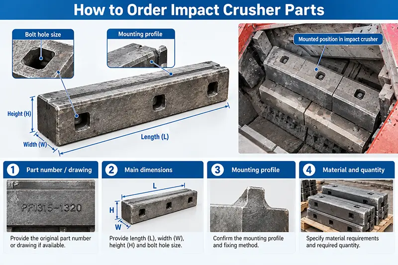
Information Required When Ordering Impact Crusher Spare Parts
Provide as much of the following information as possible:
Crusher manufacturer
Crusher model
Serial number
Part name
Original part number
Required quantity
Assembly drawing or parts-manual reference
Component dimensions
Clear photographs
Material being processed
Maximum feed size
Required product sizes
Current wear pattern
Preferred material, if already specified
Delivery country
Required delivery date
For blow bars, also provide:
Individual bar weight, when available
Mounting or locking arrangement
Working profile
Alloy specification
Orientation
Whether the bars will be installed as a complete matched set
Recommended Spare Parts Inventory
A practical spare-parts plan can divide components into three categories.
Frequently Replaced Wear Parts
Consider stocking:
Blow bars
Apron liners
Side liners
Feed-chute liners
Wear-related fasteners
Operationally Critical Service Parts
Depending on lead time and site conditions, consider:
Bearings
Seals
Belt sets
Hydraulic hoses
Locking wedges
Sensors
Adjustment components
Major Components
Rotors, shafts and bearing housings are expensive and may not need to be stored at every site. The decision depends on:
Delivery lead time
Production-loss risk
Availability of repair facilities
Condition history
Number of identical machines
Value of downtime
Stocking strategy should be based on risk and lead time—not simply the purchase price of the part.
Common Mistakes When Managing Impact Crusher Parts
Avoid the following mistakes:
Ordering parts by appearance alone
Assuming all PF-series parts are interchangeable
Selecting the hardest alloy without considering impact loading
Continuing to operate after the supporting structure is exposed
Replacing blow bars without checking weight balance
Installing new bars with damaged locking components
Ignoring uneven wear patterns
Adding lubricant without diagnosing high bearing temperature
Welding a rotor without an approved procedure
Reusing stretched or damaged fasteners
Waiting for complete part failure before ordering replacements
Keeping no record of wear measurements or replacement dates
Impact Crusher Parts for XINGAONAI PF Models
XINGAONAI’s PF impact crusher range includes models from PF1007 to PF1820, with published capacities from 30 to 800 t/h and model-specific maximum feed sizes from 300 to 800 mm.
Parts must be selected by the exact machine model and component specification. A blow bar, liner or mechanical component should not be assumed compatible across the complete model range.
When requesting parts for a XINGAONAI crusher, provide the model, serial number, part number or drawing and operating information. This allows the part dimensions and material requirements to be checked before production or shipment.
Conclusion
Impact crusher performance depends on the condition, compatibility and correct selection of its parts.
Blow bars, apron liners and side liners are replaceable wear parts. The rotor, shaft, bearings, drive system, frame and hydraulic system are major components that require appropriate inspection and condition assessment.
The most effective parts strategy is to:
Identify every component by model and part number
Match wear materials to the actual feed
Measure and record wear
Replace parts before secondary damage occurs
Maintain rotor weight balance
Keep critical spares based on lead time and production risk
Use approved procedures for major repairs
This approach helps maintain product quality, control cost per tonne and reduce unplanned downtime without relying on unsupported universal replacement intervals.