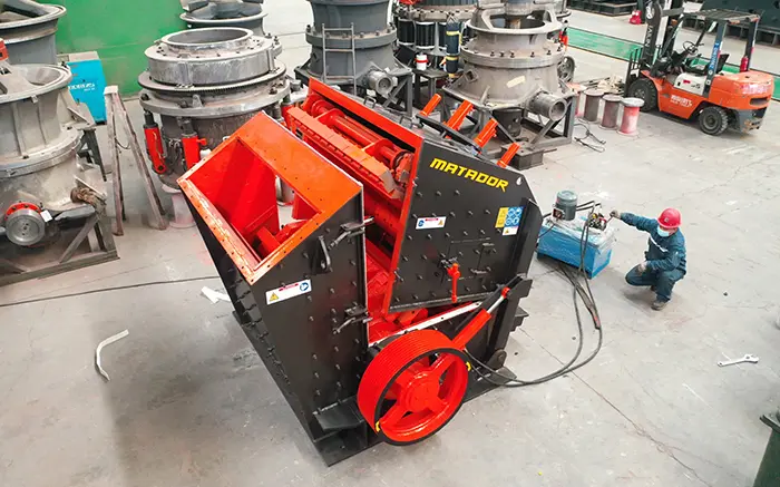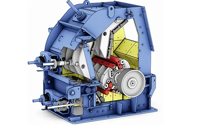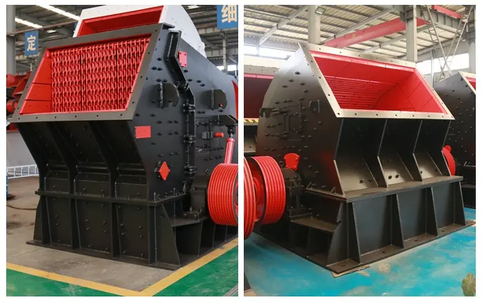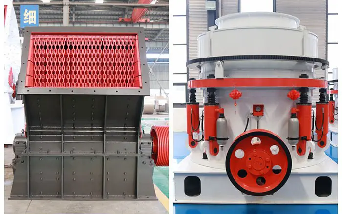
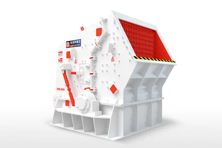
An impact crusher uses a motor-driven rotor fitted with blow bars to strike and accelerate incoming material. The broken particles are thrown against stationary impact plates, where they fracture again before rebounding through the crushing chamber. After repeated impacts, sufficiently reduced material leaves through the lower discharge area.
In simple terms, the process is:
Controlled Feeding → Blow-Bar Impact → Impact-Plate Collision → Repeated Crushing → Discharge
Unlike jaw and cone crushers, which mainly break material through compression, an impact crusher transfers the rotor’s kinetic energy directly to the feed material.
This article explains how a horizontal shaft impact crusher works, what each component does, how product size is controlled and which operating conditions affect the crushing process.
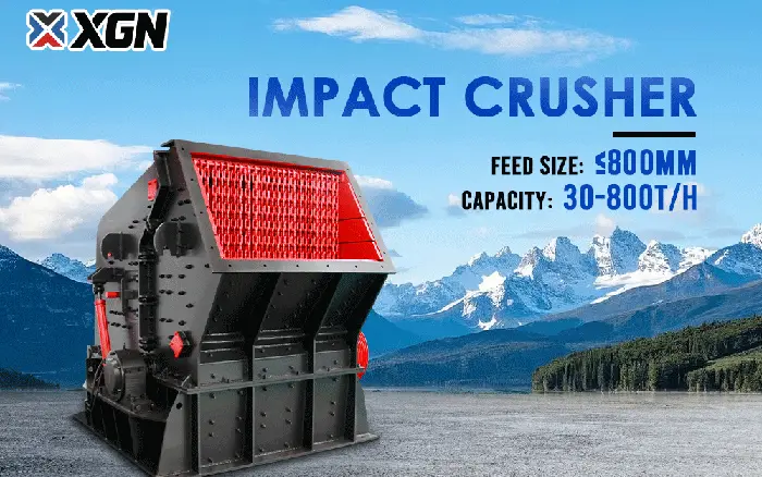
XINGAONAI’s PF Series impact crusher is designed primarily for secondary crushing of limestone, dolomite, concrete and other medium-hard materials with low to moderate abrasiveness.
What Type of Impact Crusher Does This Guide Cover?
This guide focuses on the horizontal shaft impact crusher, commonly abbreviated as HSI. XINGAONAI’s PF Series belongs to this category.
An HSI crusher has:
A horizontally arranged rotor
Blow bars mounted on the rotor
One or more impact aprons
Replaceable impact plates or breaker plates
An open lower discharge area
A motor and transmission system
A vertical shaft impact crusher, or VSI, also uses impact energy, but its rotor is arranged vertically. A VSI accelerates pre-crushed material outward and is normally used for manufactured sand, fine crushing and aggregate shaping.
HSI and VSI crushers should not be treated as the same machine. They have different internal structures, feed requirements and positions in a crushing circuit.
The Basic Impact Crusher Working Principle
The working principle is based on converting the motor’s rotational power into high-speed impact energy.
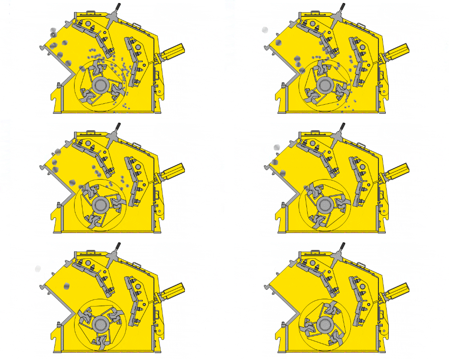
The motor drives the rotor through the transmission system. As the rotor turns, the blow bars mounted around its circumference travel through the crushing chamber at high speed.
When material enters the chamber, it meets the moving blow bars. The difference in velocity between the blow bar and the feed material produces a high-energy collision.
This initial collision:
Fractures brittle particles
Accelerates the fragments
Changes their direction
Throws them toward the impact aprons
The fragments then strike the stationary impact plates. This creates another fracture event and redirects the material toward the rotor or another part of the crushing chamber.
Material may experience several combinations of:
Blow-bar-to-material impact
Material-to-impact-plate collision
Material-to-material collision
Sliding and secondary contact inside the chamber
The exact path depends on the crusher design, rotor direction, impact-apron position, feed characteristics and operating conditions.
Main Components Involved in the Crushing Process
| Component | Function in the Working Process |
|---|---|
| Feed inlet | Directs material into the rotor’s impact zone |
| Rotor | Stores and transfers rotational energy |
| Blow bars | Strike and accelerate the feed material |
| Primary impact apron | Receives the first high-energy particle impact |
| Secondary impact apron | Provides additional size reduction and trajectory control |
| Apron adjustment system | Changes the distance between the rotor and impact apron |
| Chamber liners | Protect the crusher housing from impact and abrasion |
| Drive motor | Supplies mechanical power to the rotor |
| Transmission system | Transfers motor power to the rotor |
| Bearings and shaft | Support stable rotor rotation |
| Lower discharge area | Allows processed material to leave the chamber |
These components must function as one system. A worn blow bar, incorrectly positioned apron or unbalanced rotor can change the material trajectory and reduce crushing performance.
For a detailed explanation of individual components, wear areas and replacement information, refer to the impact crusher parts guide.
How Does an Impact Crusher Work Step by Step?
Step 1: Material Enters the Crushing Chamber
Material reaches the crusher through a feeder, chute or upstream conveyor.
The feed system should distribute material across the usable rotor width rather than concentrating it in one narrow area. Uneven feeding can produce:
Uneven blow-bar wear
Unstable motor load
Reduced capacity
Inconsistent product gradation
Localized wear inside the chamber
The maximum feed size must remain within the limit of the selected crusher model. The largest individual lump is particularly important because oversized material can damage the blow bars, restrict the inlet or overload the rotor.
A stable feed does not mean filling every available space inside the chamber. The crusher needs sufficient room for the material to accelerate, rebound and move toward the discharge.
Step 2: The Rotor Transfers Energy to the Blow Bars
The motor rotates the rotor through a belt, coupling or other transmission arrangement, depending on the equipment design.
The rotor has considerable mass and rotational inertia. As it turns, the blow bars travel along a circular path and become the principal contact points between the machine and the feed material.
Rotor speed is selected for the machine model and application. It should not be treated as one universal value for every impact crusher.
Increasing speed may increase available impact energy, but it can also:
Increase fines production
Increase blow-bar wear
Increase power demand
Change the product-size distribution
Increase sensitivity to rotor imbalance
The correct speed must remain within the equipment manufacturer’s approved range.
Step 3: Blow Bars Deliver the Initial Impact
As material enters the rotor zone, the blow bars strike it.
Part of the rotor’s kinetic energy is transferred to the material. Brittle particles develop cracks and break into smaller fragments, while the fragments are accelerated toward the impact aprons.
The effectiveness of the initial impact depends on:
Material strength
Material toughness
Particle size
Particle shape
Blow-bar profile
Rotor speed
Feed position
Blow-bar wear condition
A worn blow bar changes both the contact geometry and the material trajectory. It may reduce effective impact, increase recirculation inside the chamber and produce a coarser or less consistent discharge.
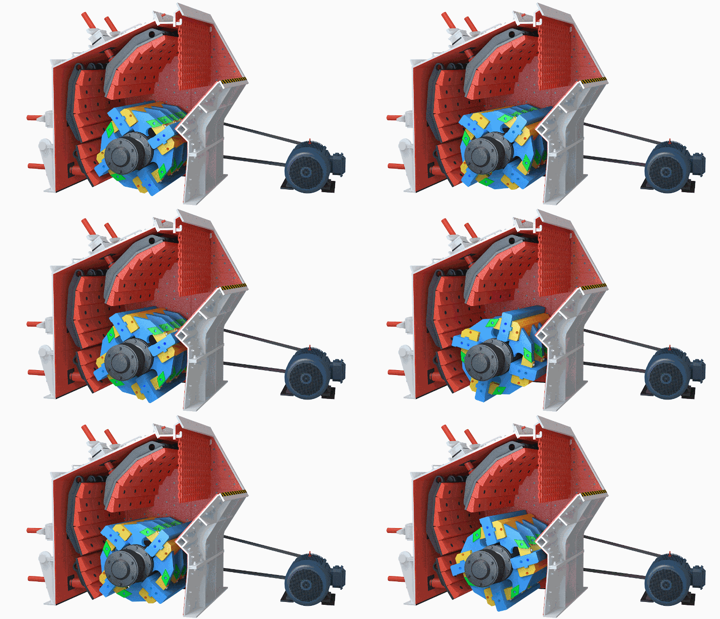
Step 4: Material Collides With the Impact Aprons
After the initial blow-bar strike, the accelerated fragments travel toward the impact aprons.
An impact apron is a stationary or adjustable assembly carrying wear-resistant impact plates. When the fragments hit these plates, they experience rapid deceleration and another high-energy collision.
This secondary impact:
Produces further fracture
Breaks weakened particles
Redirects material through the chamber
Influences the final product-size distribution
Many HSI crushers use more than one impact apron. The first apron handles relatively coarse particles and high impact loads. Subsequent aprons provide additional reduction as the material moves downward.
The number and arrangement of impact stages depend on the crusher design. They should not be confused with independent crushing machines or separate production stages.
Step 5: Particles Rebound and Are Crushed Again
Material does not normally move through the chamber in one straight path.
After striking an impact plate, particles may:
Rebound toward the rotor
Enter another blow-bar impact zone
Strike another impact apron
Collide with other moving particles
Move toward the lower discharge area
Repeated impacts gradually reduce the material.
Particle-to-particle collisions can contribute to breakage and edge reduction, but their effect varies with the material bed, feed rate and chamber design. They should not be described as a guaranteed way of eliminating wear on the metal components.
Step 6: Reduced Material Leaves the Crusher
After passing through the impact zones, material moves toward the lower discharge area.
An HSI crusher does not normally classify finished material with an internal screen. The apron gap influences reduction and product gradation, but it does not guarantee that every discharged particle has one precise size.
The final product is also affected by:
Feed-size distribution
Rotor speed
Material properties
Blow-bar condition
Impact-apron position
Feed rate
Crusher loading
Downstream screening arrangement
In a closed crushing circuit, a vibrating screen separates the required products from oversized particles. Oversized material can then be returned to the crusher for additional reduction.
How Does an Impact Crusher Produce Cubical Aggregate?
Impact crushing applies short-duration, high-energy forces rather than slowly compressing material between two surfaces.
For suitable brittle materials, these repeated impacts can break particles along natural weaknesses and reduce sharp or elongated edges. This often produces a more cubical aggregate than primary compression crushing alone.
However, particle shape is not determined by the crusher type alone. It also depends on:
Feed particle shape
Material mineralogy
Reduction ratio
Rotor speed
Apron setting
Chamber loading
Blow-bar condition
Number of crushing and screening stages
An impact crusher cannot correct every feed-shape problem through rotor speed or gap adjustment alone.
How Is Product Size Controlled?
Several variables work together to influence the discharge gradation.
| Operating Variable | General Effect |
|---|---|
| Rotor speed | Changes impact velocity, reduction and fines generation |
| Impact-apron gap | Influences the intensity of later crushing stages |
| Feed size | Oversized feed can reduce stability and increase impact loading |
| Feed gradation | Affects chamber filling and particle-to-particle contact |
| Feed rate | Influences chamber loading, throughput and product consistency |
| Material brittleness | Determines how readily particles fracture under impact |
| Material abrasiveness | Affects wear rate and operating cost |
| Blow-bar profile | Influences contact angle and material trajectory |
| Wear condition | Changes effective geometry and crushing performance |
| Closed-circuit screen | Separates final products and returns oversized material |
A smaller apron gap may increase reduction, but it can also increase fines, wear and power demand. It should not be adjusted while the crusher is operating unless the machine is specifically designed and approved for such adjustment.
Always follow the equipment manual and site isolation procedures.
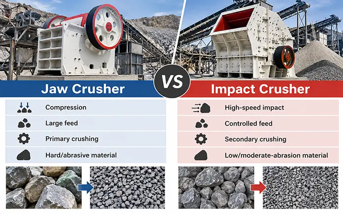
Impact Crushing vs Compression Crushing
| Feature | Impact Crusher | Jaw Crusher | Cone Crusher |
|---|---|---|---|
| Main crushing force | High-speed impact | Compression between jaw plates | Compression between mantle and concave |
| Typical crushing stage | Secondary; selected primary applications | Primary | Secondary or tertiary |
| Common feed condition | Medium-hard, brittle, low-to-moderate-abrasion material | Large, hard and abrasive feed | Hard and abrasive pre-crushed material |
| Typical product characteristic | Good particle shape for suitable material | Relatively coarse product | Controlled and consistent product gradation |
| Main wear areas | Blow bars, impact plates and liners | Jaw plates | Mantle and concave |
| Internal sizing method | Impact path and apron settings | Discharge opening | Closed-side setting |
For a complete equipment-selection analysis, see:
What Materials Are Suitable for an Impact Crusher?
Horizontal shaft impact crushers are generally well suited to materials that fracture effectively under impact and do not create excessive abrasive wear.
Common applications include:
Limestone
Dolomite
Concrete
Construction and demolition material
Asphalt
Selected sedimentary rock
Medium-hard aggregate with low to moderate abrasiveness
Materials requiring more careful evaluation include:
Granite
Basalt
Quartz-rich rock
Highly abrasive ore
Material containing large amounts of hard silica
Extremely wet or clay-rich feed
Feed containing tramp metal or uncrushable objects
An impact crusher may physically break a hard material, but that does not mean it is the most economical choice. Excessive abrasiveness can cause rapid wear of blow bars, impact plates and chamber liners.
For hard, highly abrasive material, a jaw crusher followed by a cone crusher may provide a lower wear cost.
What Factors Affect Impact Crusher Performance?
Material Characteristics
Hardness alone is not enough to predict performance. The supplier should also evaluate:
Abrasiveness
Brittleness
Mineral composition
Moisture
Clay content
Maximum lump size
Bulk density
Feed-size distribution
Two materials with similar hardness can produce very different blow-bar wear rates.
Feed Distribution
Material should be distributed across the rotor width. Concentrated feed creates uneven wear and leaves part of the rotor underutilized.
Chamber Loading
Underfeeding can reduce production and increase unnecessary metal-to-material contact. Excessive loading can restrict material movement, increase motor load and produce an unstable discharge.
Blow-Bar Condition
Worn, damaged or unevenly installed blow bars change rotor balance and material trajectory. Blow bars should be evaluated by measured wear and manufacturer limits rather than a universal replacement interval.
Rotor Balance
The rotor and installed blow bars must remain balanced. Unequal wear or incorrectly matched blow bars can cause vibration and increase loads on bearings, the shaft and the crusher frame.
Impact-Apron Condition
Worn impact plates or incorrect apron positioning can reduce crushing efficiency and produce an inconsistent product.
Moisture and Clay
Moderate moisture may be manageable, but excessive moisture or clay can cause buildup inside the chamber and discharge area. Material testing and suitable chute design may be required.
Downstream Discharge
A restricted conveyor or blocked discharge area can cause material to accumulate under the crusher. The complete crushing line should be checked rather than treating the crusher as an isolated machine.
Detailed inspection and troubleshooting procedures are covered in the impact crusher maintenance checklist.
How an Impact Crusher Works in a Crushing Plant
An impact crusher normally operates as part of a complete process rather than as a standalone machine.
A typical secondary impact-crushing circuit is:
Hopper → Feeder → Jaw Crusher → Impact Crusher → Vibrating Screen → Product Conveyors
The jaw crusher reduces the largest feed material. The impact crusher then provides secondary reduction and particle-shape improvement. The screen separates the required products and returns oversized particles when a closed circuit is used.
In selected low-abrasion applications, a large impact crusher may receive material directly after the feeder. This should only be considered after evaluating:
Maximum lump size
Material abrasiveness
Drop height
Required reduction ratio
Blow-bar wear
Rotor and drive capacity
Required final products
Plant availability requirements
For further information, see the guide to primary and secondary impact crusher applications.
XINGAONAI PF Series Impact Crusher
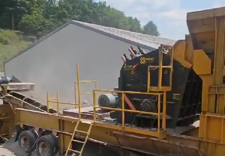
XINGAONAI’s PF Series is a horizontal shaft impact crusher designed primarily for secondary crushing.
The published product range includes:
Models from PF1007 to PF1820
Maximum feed sizes from 300 to 800 mm, depending on model
Published capacities from 30 to 800 t/h
Motor powers selected according to the model
Adjustable impact-apron configurations
Access to the crushing chamber for inspection and wear-part replacement
These figures describe the published model range. They are not guaranteed performance values for every material.
Actual capacity and product gradation depend on:
Feed material
Feed-size distribution
Moisture
Abrasiveness
Rotor configuration
Apron setting
Required product size
Screening circuit
Operating conditions
A model should therefore be selected using project-specific material and process information.
Common Signs That the Crushing Process Is Not Working Correctly
| Symptom | Possible Cause |
|---|---|
| Product becomes coarser | Worn blow bars, enlarged apron gap or excessive feed |
| Excessive fines | High rotor speed, narrow apron setting or fragile feed |
| Uneven product size | Unstable feed, uneven wear or incorrect apron position |
| Increasing motor current | Overfeeding, buildup, restricted discharge or mechanical resistance |
| Abnormal vibration | Uneven blow-bar wear, rotor imbalance, loose parts or bearing problems |
| Capacity decreases | Worn wear parts, wet feed, blocked discharge or inconsistent feeding |
| Wear is concentrated on one side | Off-center feed or uneven distribution across the rotor |
| Metallic impact noise | Loose component, tramp metal or damaged wear part |
These symptoms can have multiple causes. The crusher should be safely isolated before guards are removed or internal components are inspected.
Conclusion
An impact crusher works by using a motor-driven rotor and blow bars to transfer high-speed impact energy to the feed material.
The first blow-bar strike fractures and accelerates the material. The fragments then collide with impact aprons, rebound through the chamber and undergo additional impacts before leaving through the lower discharge area.
Reliable operation depends on more than rotor speed. Feed distribution, material abrasiveness, blow-bar condition, impact-apron position, rotor balance and downstream screening all influence capacity and final product quality.
For PF Series model selection, provide XINGAONAI with the material name, maximum feed size, required capacity, moisture, abrasiveness, target product sizes and crushing-plant layout.