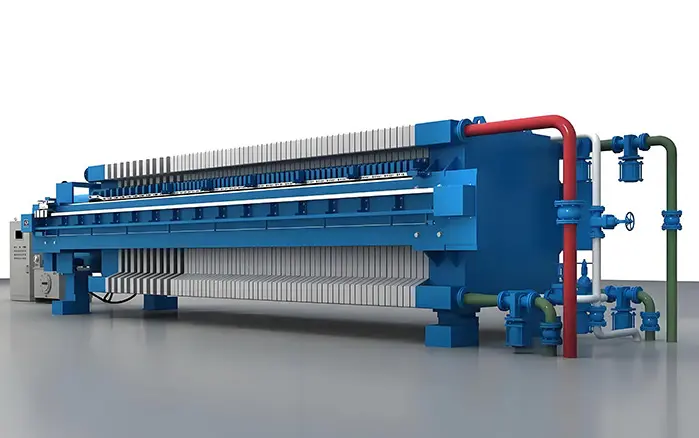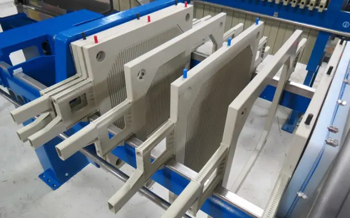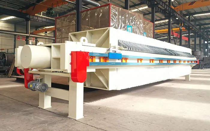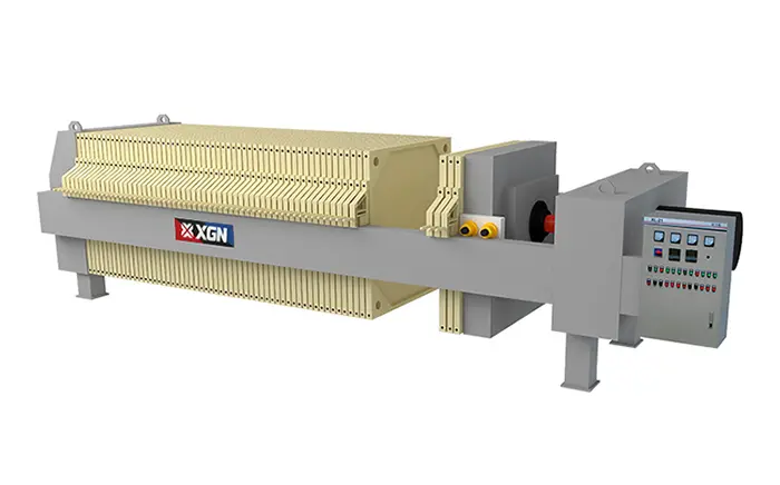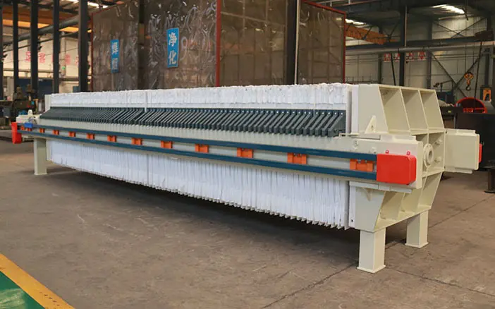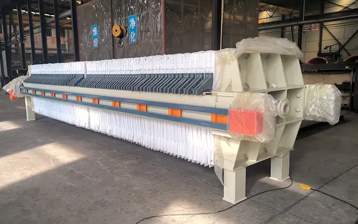
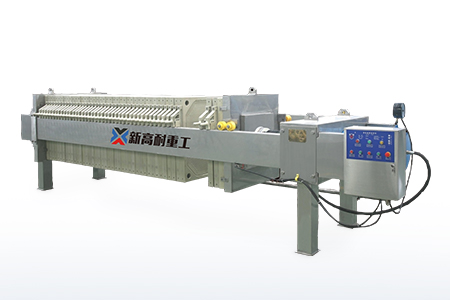
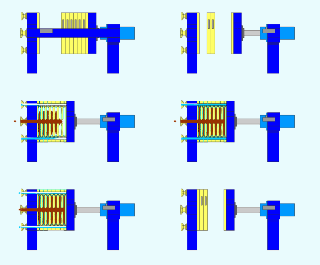
A plate and frame filter press separates suspended solids from liquids through pressure-driven batch filtration. Alternating filter plates and hollow frames are assembled into a plate pack, with filter cloth installed between each plate and frame.
Before filtration begins, a hydraulic or mechanical closing system compresses the plate pack. A feed pump then delivers slurry into the hollow frames. Liquid passes through the filter cloth and drainage grooves as filtrate, while solid particles remain inside the frames and gradually form filter cakes.
When the selected filtration endpoint is reached, slurry feeding stops, internal pressure is released, and the press opens for cake discharge.
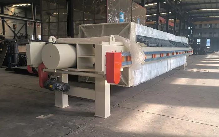
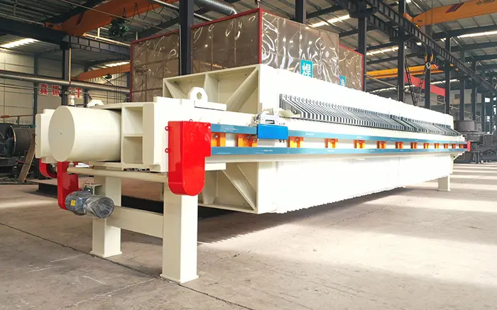
XINGAONAI supplies an industrial Plate and Frame Filter Press for mineral concentrate, tailings, coal slime and industrial-slurry dewatering.
Plate and Frame Filter Press Working Principle at a Glance
The complete filtration cycle can be summarized as:
Plate closing → Slurry feeding → Filtrate separation → Cake formation → Filtration endpoint → Pressure release → Cake discharge → Cloth inspection
Two separate systems are involved:
The closing system compresses and holds the plate-and-frame pack in position.
The slurry feed pump generates the pressure required for filtration.
The hydraulic closing system does not directly force liquid through the filter cloth. Filtration pressure is created on the slurry side by the feed pump.
Main Components Involved in the Filtration Process
| Component | Function in the filtration process |
|---|---|
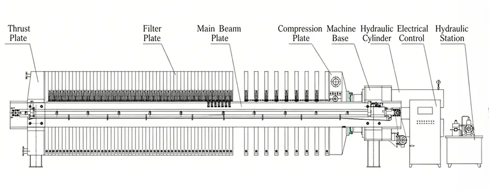
| Filter plate | Supports the filter cloth and provides channels for filtrate drainage |
| Hollow frame | Forms the space where slurry enters and filter cake accumulates |
| Filter cloth | Retains solid particles while allowing liquid to pass |
| Closing system | Compresses and holds the plate-and-frame pack closed |
| Feed pump | Delivers slurry and generates slurry-side filtration pressure |
| Feed manifold | Distributes slurry to the individual frames |
| Filtrate outlets | Collect and discharge the separated liquid |
| Control system | Controls the selected closing, feeding and opening sequence |
| Plate-shifting system | Separates plates and frames during cake discharge when fitted |
The plate-and-frame arrangement is what distinguishes this design from a recessed chamber filter press. In a true plate and frame press, separate hollow frames provide the space in which the filter cake forms.
For detailed information about the machine structure, see the plate and frame filter press construction guide.
Step 1: Closing the Plate-and-Frame Pack
The filtration cycle begins by arranging the filter plates, hollow frames and filter cloths in the correct sequence.
A typical arrangement is:
Filter plate → Filter cloth → Hollow frame → Filter cloth → Filter plate
The closing system moves the follower or moving head toward the fixed head, compressing the complete plate-and-frame pack. This keeps the filter cloth and sealing surfaces in position during slurry feeding.
The closing mechanism may be hydraulic or mechanical, depending on the machine configuration. Its purpose is to hold the pack securely closed against the slurry-side pressure generated during filtration.
The closing system does not squeeze water out of the filter cake. That additional squeezing action is associated with membrane filter presses, not a standard plate and frame filter press.
Before feeding begins, operators should confirm that:
Plates and frames are correctly aligned.
Filter cloths are flat and correctly installed.
No residual cake is present on the sealing surfaces.
The plate pack has reached the specified closing condition.
The filtrate outlets and feed line are correctly configured.
Step 2: Feeding Slurry into the Frames
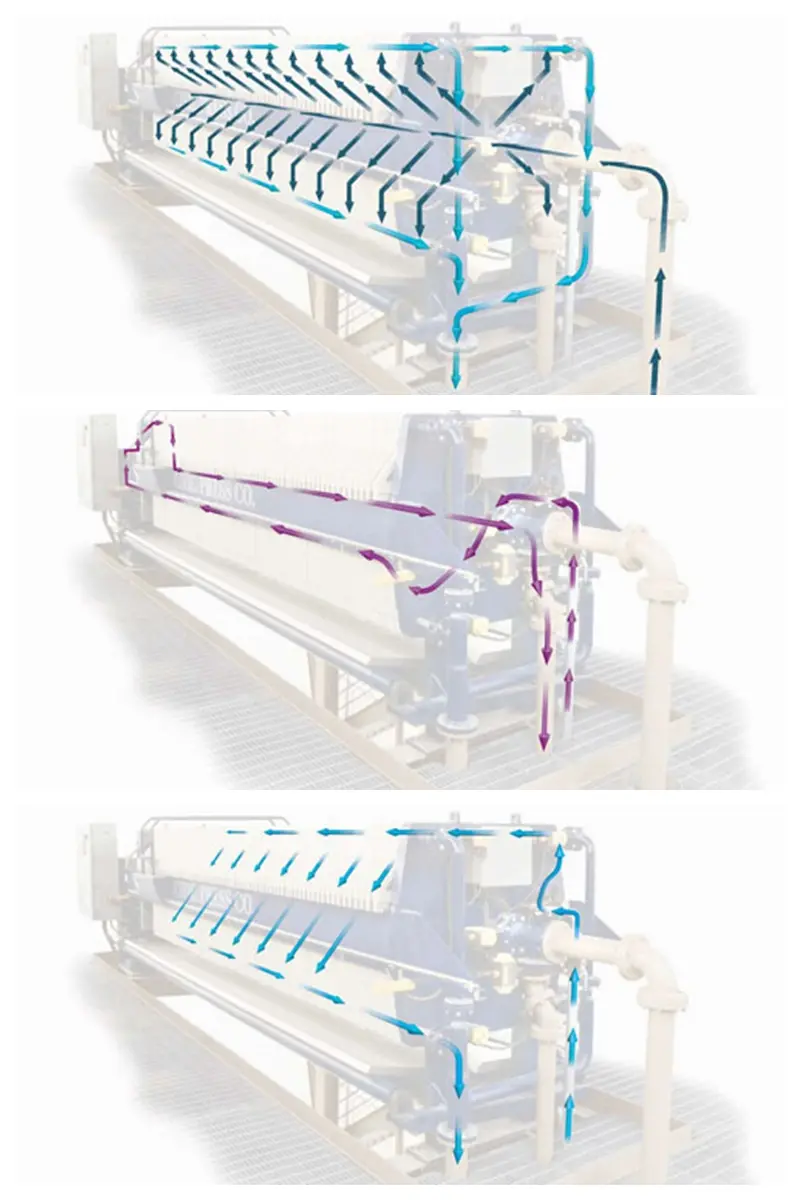
After the plate-and-frame pack has been closed, the feed pump delivers slurry into the press through the feed manifold.
The slurry flows through the feed channel and enters the hollow frames. These frames provide the volume in which solid particles accumulate during the filtration cycle.
Feeding should begin under controlled conditions so the frames fill as evenly as possible. Sudden or excessive pressure at startup may contribute to:
Leakage between plates and frames
Filter-cloth displacement
Uneven chamber filling
Uneven cake formation
Damage to plates, frames or cloths
The correct feed rate and maximum feed pressure depend on the selected machine, slurry properties and filter-cloth configuration. Operators should follow the model-specific limits instead of applying a universal pressure setting.
Step 3: Liquid Passes Through the Filter Cloth
As the feed pump continues supplying slurry, pressure develops on the slurry side of the filter cloth.
The resulting pressure difference causes liquid to pass through the porous cloth. Solid particles that are too large to pass through the cloth are retained on its surface.
The separated liquid follows this path:
Slurry inside the frame → Filter cloth → Drainage grooves on the filter plate → Filtrate outlet
The solid phase follows a different path:
Slurry inside the frame → Solids retained on the cloth → Filter cake formed inside the frame
At the beginning of the cycle, a small quantity of fine particles may pass through the cloth until an initial solids layer forms. As this layer develops, it becomes part of the filtration medium and may improve solid retention.
Filtrate clarity depends on several factors:
Particle-size distribution
Filter-cloth material and permeability
Cloth installation
Feed-pressure stability
Cake formation
Damage or wear in the filter cloth
Sealing condition of the plate-and-frame pack
Cloudy filtrate should not automatically be treated as normal. Persistent turbidity may indicate damaged cloth, improper installation, bypass or an unsuitable filtration medium.
Step 4: Filter Cake Formation
The solids retained by the filter cloth begin forming layers on both sides of each hollow frame.
As filtration continues, these layers grow inward until the available frame volume is filled. The accumulated solid material is known as the filter cake.
During cake formation:
Cake thickness increases.
Resistance to liquid flow increases.
Filtrate flow normally decreases.
Feed-pump pressure may rise or stabilize.
The amount of additional liquid removed per unit of time declines.
The filter cake itself becomes part of the filtration barrier. This may improve particle retention, but it also increases resistance to filtrate flow.
Cake formation is influenced by:
Slurry solids concentration
Particle size and shape
Particle-size distribution
Slurry viscosity
Feed pressure
Filter-cloth permeability
Frame thickness
Filtration time
Chemical pretreatment, where applicable
A thicker frame provides more cake volume per cycle, but a thicker cake may require more time to fill and may retain more moisture. The optimal frame thickness therefore depends on the slurry and production objective.
Step 5: Determining the Filtration Endpoint
Filtration should not always continue until the equipment reaches its maximum allowable pressure.
The endpoint may be determined using one or more of the following signals:
Filtrate flow falls below a selected value.
Feed pressure stabilizes.
The planned filtration time has elapsed.
The frames have reached the expected filling condition.
The required cake condition has been achieved.
The control system reaches a process-specific endpoint.
The correct endpoint depends on the material and operating objective.
For example, a process focused on recovering valuable solids may use different endpoint criteria from a wastewater process focused on filtrate clarity. A slurry containing fine particles may also require a longer cycle than a slurry containing coarse, readily filterable solids.
Filtration testing is recommended when a guaranteed throughput, filtrate quality or cake-moisture target is required.
Step 6: Stopping the Feed and Releasing Pressure
Once the filtration endpoint has been reached, the feed pump is stopped and the slurry feed line is isolated according to the operating procedure.
The press must not be opened while pressure remains inside the filtration chambers.
Before opening:
Stop slurry feeding.
Isolate the feed line.
Release trapped slurry-side pressure.
Confirm that the pressure gauge has returned to a safe state.
Follow the site’s energy-isolation procedure.
Confirm that no stored hydraulic or mechanical energy can cause unexpected movement.
The hydraulic closing system and the slurry feed system are different pressure systems. Both must be handled according to the equipment manual and site safety procedures.
Step 7: Opening the Press and Discharging the Cake
After pressure has been safely released, the closing system retracts and the plate-and-frame pack opens.
The plates and frames are then separated manually or with an automatic shifting mechanism. Filter cakes are removed from the hollow frames.
Free-releasing cakes may fall under gravity. Sticky, thin or incompletely formed cakes may require controlled manual assistance or adjustments to the filtration process.
Difficult cake discharge may be associated with:
Unsuitable filter cloth
Incomplete cake formation
Sticky or fine material
Excessive residual moisture
Damaged or blinded cloth
Irregular frame filling
Material remaining on sealing surfaces
Operators should not strike plates or frames with unsuitable tools because impact can damage the filtration surfaces or cause cracks.
Step 8: Inspecting and Cleaning the Filter Cloth
After cake discharge, the filter cloth, plates, frames and sealing surfaces should be inspected.
The inspection should look for:
Cake residue on sealing edges
Tears or holes in the cloth
Wrinkled or displaced cloth
Blocked drainage grooves
Cracks or deformation
Uneven cake thickness
Signs of leakage
Accumulated solids in feed channels
Cleaning frequency depends on the slurry and cloth condition. Some materials release cleanly, while fine, sticky or chemically reactive solids may require more frequent washing.
The press can be closed for the next cycle after the filtration surfaces have been checked and prepared.
For the complete startup, monitoring, shutdown and cake-discharge procedure, see the plate and frame filter press operation guide.
Understanding the Different Pressures
Several pressure-related terms are used when describing a filter press. They should not be treated as interchangeable.
| Pressure term | Source | Function |
|---|---|---|
| Hydraulic system pressure | Hydraulic pump | Operates the closing cylinder |
| Plate closing force | Closing cylinder and press frame | Holds the plate-and-frame pack closed |
| Slurry feed pressure | Slurry feed pump | Moves slurry into the hollow frames |
| Filtration pressure | Slurry-side pressure across the cake and filter cloth | Drives liquid through the filtration path |
Hydraulic system pressure may be expressed in MPa or bar, while plate closing force should normally be expressed as force, such as kN.
The correct operating limits depend on:
Filter-press model
Plate and frame material
Filter-cloth configuration
Feed-pump characteristics
Slurry properties
Piping design
Safety settings
Operators must not copy pressure settings from another machine or application.
Factors Affecting the Filtration Process
Slurry Solids Concentration
Slurry with a low solids concentration contains more liquid relative to the amount of cake-forming material. More slurry may therefore need to pass through the press to produce a complete cake.
A higher solids concentration may increase cake formation speed, but it can also change slurry viscosity and feed behavior.
Particle-Size Distribution
Fine particles generally create a cake with smaller flow paths and higher resistance. This can reduce filtrate flow and extend the filtration cycle.
A mixture of coarse and fine particles may form a different cake structure from a narrowly distributed fine slurry. Particle size should therefore be evaluated together with solids concentration and viscosity.
Filter-Cloth Selection
The filter cloth is the primary filtration medium. Its performance depends on:
Material
Yarn type
Weave
Air permeability
Surface treatment
Chemical compatibility
Temperature resistance
Cake-release characteristics
A cloth that provides very clear filtrate may also produce slower filtration. Selection should balance filtrate quality, throughput, cake release and cloth life.
Slurry Viscosity and Temperature
Higher viscosity generally reduces the rate at which liquid passes through the filter cloth and filter cake.
Temperature may affect viscosity, chemical compatibility and cloth performance. Any temperature adjustment must remain within the limits of the slurry, filter cloth, plates, frames, piping and seals.
Feed Pressure
Feed pressure provides the driving force for filtration. Increasing pressure may improve liquid flow within the safe operating range, but higher pressure does not always create a proportionally drier cake.
Excessive pressure can contribute to:
Leakage
Cloth displacement
Plate or frame damage
Feed-line failure
Unsafe operating conditions
The maximum allowable feed pressure must never be exceeded.
Frame Thickness
Frame thickness determines the available cake volume in each chamber.
Thicker frames can hold more solids per cycle, but they may require longer filling and filtration times. Thinner frames may fill more quickly but require more frequent cake-discharge cycles.
Model selection should consider daily dry-solids throughput, cycle time and required cake characteristics—not filtration area alone.
Plate and Frame vs Chamber vs Membrane Filter Press
These filter presses all use pressure filtration, but their cake chambers are formed differently.
| Filter press type | How the cake chamber is formed | Additional squeezing |
|---|---|---|
| Plate and frame filter press | Separate hollow frames are installed between filter plates | Normally no membrane squeezing |
| Recessed chamber filter press | Recesses in adjacent filter plates form the chambers | Normally no membrane squeezing |
| Membrane filter press | Chambers include flexible membrane plates | Membranes apply additional pressure after initial filtration |
A membrane filter press is still generally a batch-filtration machine. Its additional squeezing stage should not be confused with the hydraulic system used to close a standard plate and frame press.
Conclusion
The plate and frame filter press working principle is based on pressure-driven batch filtration.
Separate hollow frames form the cake chambers, while filter plates support the cloth and provide filtrate drainage paths. The closing system holds the plate pack securely in position, and the feed pump creates the slurry-side pressure that drives liquid through the filter cloth.
Solid particles remain inside the frames and form filter cakes. When the filtration endpoint is reached, feeding stops, pressure is released, and the press opens for cake discharge.
Filtration performance depends on the slurry, particle-size distribution, solids concentration, viscosity, filter-cloth selection, frame thickness, feed pressure and cycle time. For this reason, model selection should be based on actual process data and, when necessary, laboratory or pilot filtration testing.
Review the available industrial plate and frame filter press models and provide your slurry data, target throughput and required cake condition for equipment selection.