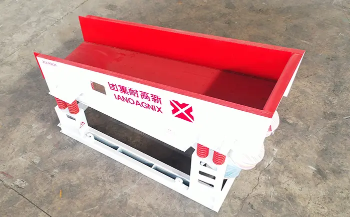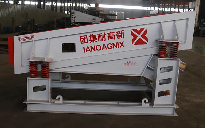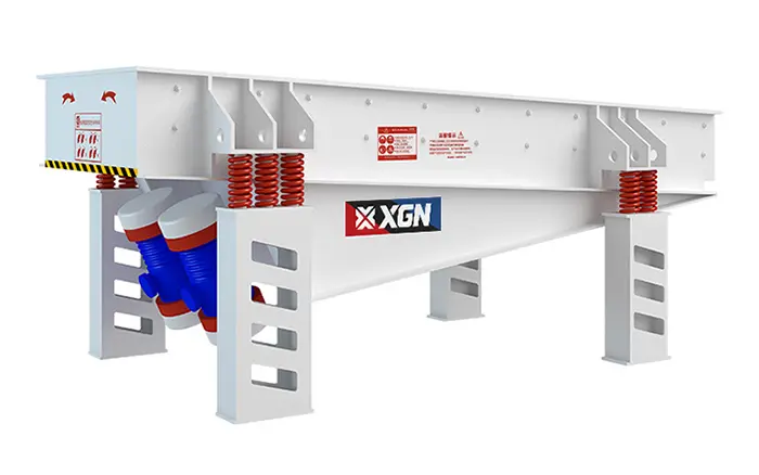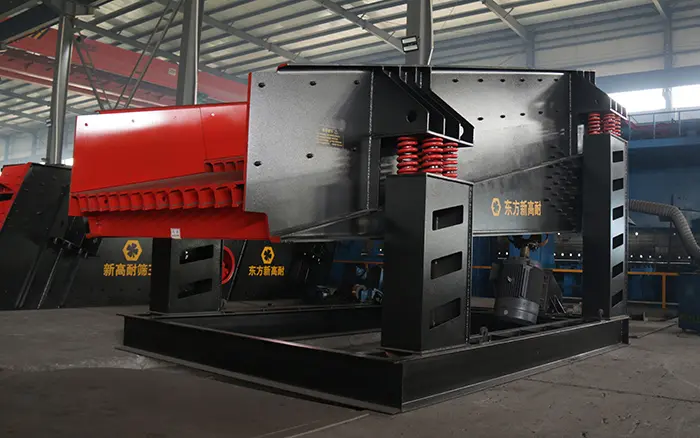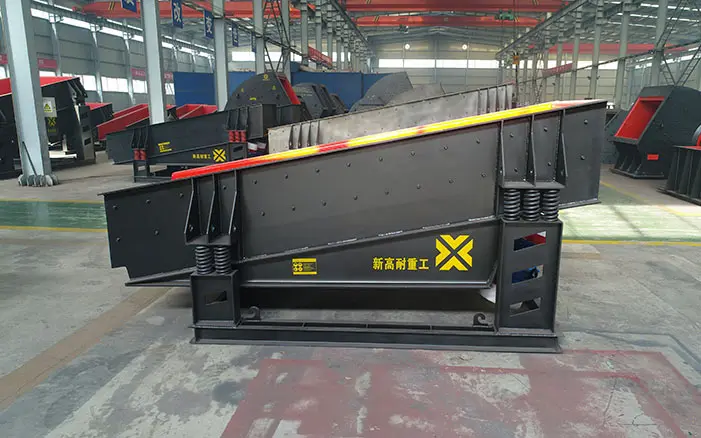
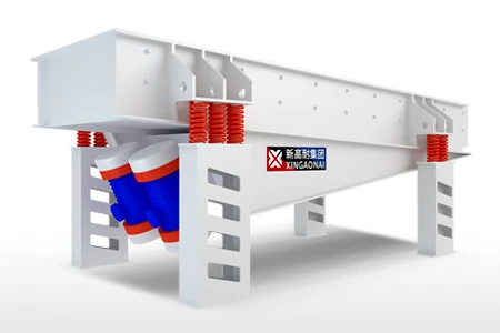
A mining vibrating feeder is installed between a storage hopper and downstream processing equipment to deliver ore, rock or aggregate at a controlled and continuous rate.
Although the feeder appears to be a relatively simple component, its performance can directly affect the productivity of the entire crushing plant. An undersized feeder may restrict plant capacity, while an incorrectly designed hopper-feeder interface can cause bridging, uneven flow, excessive impact wear and unstable crusher loading.
Selecting the right feeder therefore requires more than checking the required capacity. Feed size, bulk density, moisture, clay content, abrasiveness, hopper pressure, impact load, installation angle and the type of downstream crusher must all be considered.
This guide explains how a mining vibrating feeder works, where it is used and how to select an appropriate configuration for a mining or aggregate processing plant.
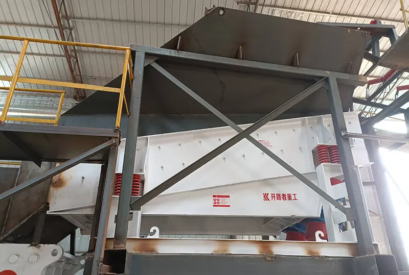
What Is a Mining Vibrating Feeder?
A mining vibrating feeder is a material-handling machine that uses controlled vibration to move bulk material from a hopper or stockpile toward a crusher, conveyor, screen or processing unit.
Unlike a conventional belt conveyor, the feeder is designed to regulate the discharge rate and withstand the impact of material falling from a hopper. Depending on the configuration, it may also remove fines before primary crushing.
The basic equipment is similar to a standard vibrating feeder, but a mining application normally requires a reinforced structure, abrasion-resistant liners and a drive system suitable for continuous heavy-duty operation.
For a more general explanation of the equipment, read what is a vibrating feeder.
What Does a Vibrating Feeder Do in a Mining Plant?
The primary purpose of a mining feeder is to maintain a stable material flow between two process stages. In a typical primary crushing plant, the feeder is installed below the receiving hopper and ahead of the primary crusher.
Its main functions include:
Receiving ore or rock discharged from trucks, loaders or upstream conveyors
Regulating the amount of material entering the crusher
Reducing sudden surges that may overload the crusher
Distributing material more evenly across the crusher inlet
Removing undersized material before crushing when a grizzly section is installed
Protecting downstream conveyors and processing equipment from unstable loading
Allowing the plant operator to adjust the production rate
Without a properly selected feeder, the primary crusher may alternate between being overloaded and running partially empty. This reduces overall plant efficiency and can increase wear on the crusher, motors, belts and supporting structures.
How Does a Mining Vibrating Feeder Work?
A vibrating feeder uses a drive system to generate repeated vibration in the feeder trough or body. The vibration moves material forward through a combination of lifting, sliding and short forward movements.
The feed rate is affected by several factors:
Vibration frequency
Vibration amplitude
Feeder inclination
Material depth
Hopper opening
Material bulk density
Moisture and clay content
Drive configuration
Feeder dimensions
In many mining installations, the feed rate can be adjusted by changing the drive output or using a frequency-control system. This allows the operator to match feeder output to the capacity of the downstream crusher or conveyor.
This page focuses on mining applications and equipment selection. For a detailed explanation of the operating mechanism, see the vibrating feeder working principle.
Main Types of Mining Vibrating Feeders
Mining feeders are available in several configurations. The correct type depends on material characteristics, required capacity and whether fines need to be removed before crushing.
1. Vibrating Pan Feeder
A vibrating pan feeder has a solid feeding surface without screening openings. It is used when all material must be delivered to the next processing stage.
Pan feeders are commonly installed:
Under storage bins
Below surge hoppers
Ahead of secondary or tertiary crushers
Before conveyors
In controlled aggregate feeding applications
The feeder pan can be fitted with replaceable liners to protect the main structure from abrasive material.
2. Vibrating Grizzly Feeder
A vibrating grizzly feeder combines feeding and preliminary screening. The front section receives and transports the material, while the grizzly bars allow smaller particles to fall through before the oversized material enters the crusher.
Removing fines before primary crushing can:
Reduce unnecessary crusher loading
Increase usable crusher capacity
Reduce wear inside the crushing chamber
Improve downstream screening efficiency
Allow fines to bypass the primary crusher
The opening between the bars must be selected according to the desired separation size and the minimum particle size that should enter the crusher.
More information about this configuration can be found in the guide to a vibrating feeder with a screening section.
3. Heavy-Duty Vibrating Feeder
Heavy-duty feeders are designed for coarse, dense and abrasive materials. They normally use reinforced side plates, stronger cross-members, wear-resistant liners and a drive system selected for high continuous loads.
These feeders are commonly used for:
Run-of-mine ore
Blasted quarry rock
Iron ore
Copper ore
Granite
Basalt
Hard limestone
Other coarse abrasive materials
The structure must be evaluated according to both the normal operating load and the impact created when large rocks fall into the feeder.
4. Linear Vibrating Feeder
A linear feeder moves material along a controlled straight path. Depending on its construction, it may be used for shorter transfer distances, controlled process feeding or applications requiring relatively consistent material distribution.
The motion characteristics and installation requirements are explained further in the linear vibrating feeder guide.
Materials a Mining Vibrating Feeder Can Handle
Mining vibrating feeders can process many types of ore, rock and aggregate. However, every material behaves differently inside a hopper and on a vibrating feeding surface.
| Material condition | Main design concern | Recommended consideration |
|---|---|---|
| Large blasted rock | High impact and irregular lump size | Reinforced impact zone and correct maximum feed opening |
| Iron or copper ore | High bulk density and abrasion | Heavy structure and wear-resistant liners |
| Granite or basalt | High hardness and abrasive wear | Replaceable liners and reinforced feeding surface |
| Limestone | Variable lump size and fines content | Select feeder width and grizzly opening according to crusher requirements |
| Wet ore | Reduced flow and material adhesion | Check moisture level, hopper angle and operating amplitude |
| Clay-rich material | Bridging and buildup | Conduct material testing and consider an alternative feeder when necessary |
| Fine aggregate | Dust and uncontrolled flow | Use appropriate sealing and feed-rate control |
| Mixed recycled material | Irregular shape and composition | Inspect for oversized or foreign objects before feeding |
Dry, free-flowing rock is generally easier to feed than wet, sticky or clay-rich material. A feeder that performs well with dry granite may not deliver the same capacity when handling wet ore containing a high percentage of fines.
For difficult materials, the supplier should evaluate actual samples or detailed material information before confirming a model.
How to Select a Mining Vibrating Feeder
A reliable feeder selection should be based on the operating conditions of the complete plant rather than a single capacity figure.
1. Determine the Required Capacity
The feeder must deliver enough material to support the target output of the downstream crusher or processing unit.
Required information includes:
Average plant production rate
Maximum instantaneous feed rate
Expected operating hours
Upstream loading method
Crusher capacity
Planned production expansion
A feeder should not be selected only according to average production. Truck dumping, loader cycles and variations in material density can create temporary surge loads considerably higher than the average rate.
The selected feeder should provide sufficient operating range without constantly running at its maximum setting.
2. Identify the Maximum Feed Size
Maximum lump size affects:
Feeder width
Side-wall height
Hopper outlet dimensions
Impact-zone design
Liner thickness
Grizzly-bar spacing
Downstream crusher opening
The largest occasional rock should also be considered. A single oversized lump may block the hopper outlet even when most of the feed is considerably smaller.
3. Confirm the Bulk Density
Capacity measured in tonnes per hour depends on material density.
Two materials occupying the same volume may have very different weights. A feeder selected by volume alone may therefore be overloaded when handling dense ore.
Provide both the loose bulk density and, when available, the compacted bulk density.
4. Evaluate Moisture and Clay Content
Moisture can change material flow dramatically. Fine wet particles may adhere to the hopper wall, feeder pan or grizzly bars.
This can lead to:
Reduced effective capacity
Uneven feeding
Grizzly opening blockage
Material buildup
Increased cleaning requirements
Bridging inside the hopper
When moisture or clay is present, provide the expected operating range rather than only the average value.
5. Assess Abrasiveness
Highly abrasive material wears the feeder pan, liners, grizzly bars and discharge area.
Wear protection may include:
Replaceable steel liners
Thicker liners in the impact zone
Abrasion-resistant materials
Modular grizzly bars
Reinforced discharge sections
The liner design should balance wear life, replacement cost and equipment weight.
6. Calculate Hopper Pressure and Head Load
A feeder installed below a deep hopper is affected by the vertical pressure of the stored material.
An excessively large hopper opening can place too much material weight on the feeder, restrict movement and increase structural stress. An opening that is too small may cause bridging or limit capacity.
The feeder and hopper must therefore be designed as one material-flow system.
7. Check the Material Drop Height
Material falling directly from a truck or high hopper can create severe impact.
A large drop height may cause:
Feeder deck deformation
Liner damage
Structural cracking
Damage to grizzly bars
Excessive vibration transfer
Premature bearing or spring failure
The impact point should be reinforced, and the hopper design should reduce direct impact on vulnerable components where possible.
8. Decide Whether Pre-Screening Is Required
If the feed contains a large quantity of particles already smaller than the crusher’s target feed size, a vibrating grizzly feeder may be more efficient than a solid pan feeder.
Important information includes:
Percentage of fines
Required separation size
Moisture content
Shape of the particles
Downstream fines-handling arrangement
A screening section should only be used when the separated material has a clear route to a bypass conveyor, chute or stockpile.
9. Review the Installation Layout
The available space affects feeder length, width, support arrangement and discharge height.
The layout review should include:
Hopper dimensions
Foundation location
Crusher inlet position
Discharge chute angle
Service access
Liner replacement space
Motor access
Dust collection
Drainage
Cable routing
Matching the Feeder to the Primary Crusher
The feeder and primary crusher must be selected as a coordinated system.
A feeder that delivers more material than the crusher can process will cause material buildup or crusher overloading. A feeder with insufficient capacity will leave the crusher underfed and reduce plant output.
The following points should be checked:
Feeder maximum capacity versus crusher capacity
Crusher feed-opening dimensions
Maximum acceptable lump size
Required material distribution across the crusher inlet
Percentage of fines bypassing the crusher
Discharge height and trajectory
Feed-rate control method
Emergency stop and interlock logic
Where possible, the feeder speed should respond to the operating condition of the crusher. Motor current, chamber level or another suitable plant signal may be used as part of the control strategy.
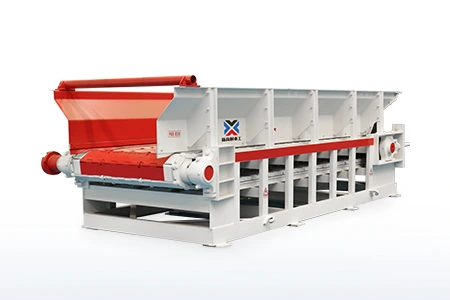
Vibrating Feeder vs. Apron Feeder
A vibrating feeder is not the best choice for every mining application. Severe impact, very large lumps, high static head load or particularly sticky material may require an apron feeder.
| Selection factor | Vibrating feeder | Apron feeder |
|---|---|---|
| Typical material | Rock, ore and aggregate with reasonable flow characteristics | Large, heavy, abrasive or difficult material |
| Feeding action | Material moves through vibration | Material is carried by overlapping pans and chains |
| Pre-screening option | Available with a grizzly section | Normally requires separate screening |
| Installation weight | Generally lower | Generally higher |
| Impact resistance | Depends on structure and impact-zone design | Usually preferred for severe impact loads |
| Sticky material | Requires careful evaluation | May be more suitable in certain difficult applications |
| Maintenance focus | Drive, springs, liners, fasteners and grizzly bars | Chains, rollers, pans, sprockets and lubrication |
| Typical investment | Usually lower for comparable conventional applications | Usually higher but suitable for more severe duty |
XINGAONAI offers both the ZG Series Vibrating Feeder and the BLG Series Apron Feeder.
If the application involves a high hopper load or severe impact, review the apron feeder working principle before making the final selection.
XINGAONAI ZG Series Vibrating Feeder Selection
The published XINGAONAI product range includes ZGCX, ZGCW and ZGXG feeder models for different capacity and feed-size requirements.
| Series | Published capacity range | Published maximum feed size |
|---|---|---|
| ZGCX Series | 150–3000 t/h | 500–1600 mm, depending on model |
| ZGCW Series | 80–800 t/h | 500–1200 mm, depending on model |
| ZGXG Series | 150–600 t/h | Up to 200 mm |
These figures show the overall range of the available models. They should not be used as the only selection criteria.
The final model must be confirmed according to:
Material bulk density
Maximum lump size
Moisture and clay content
Required capacity
Hopper opening
Hopper head load
Feeder inclination
Impact conditions
Screening requirements
Downstream equipment
A model rated for a certain capacity under one material condition may deliver a different output when handling material with another density, moisture level or particle-size distribution.
Hopper and Feeder Interface Design
Many feeder problems are caused by the hopper interface rather than the feeder itself.
The hopper outlet must allow material to flow evenly onto the feeder without placing excessive static pressure on the vibrating body.
Important design points include:
Hopper Outlet Size
The outlet must be large enough to prevent bridging but controlled enough to avoid excessive bed depth and head load.
Material Impact Point
The main impact area should be positioned over a reinforced section of the feeder. Large rocks should not fall directly onto the discharge end, drive system or unsupported plate sections.
Material Bed Depth
A stable bed of material can protect the feeder surface from direct impact. However, excessive bed depth increases the load and may restrict vibration.
Clearance Around the Feeder
The vibrating body must have enough clearance to move freely without contacting fixed chutes, guards or support structures.
Discharge Chute Alignment
The discharge chute must direct material into the crusher or conveyor without causing spillage, blockage or uneven loading.
Dust and Water Management
Dust covers, extraction points and water drainage should be included where required. Covers and chutes must not restrict feeder movement.
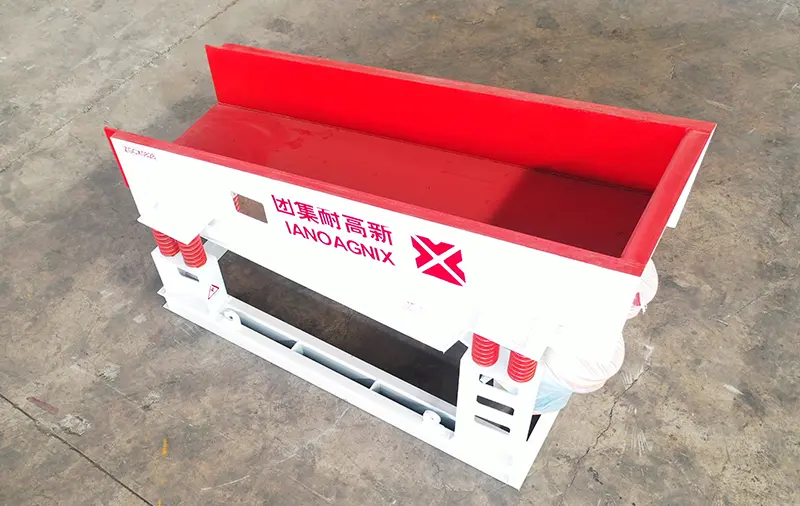
Installation and Commissioning Checklist
Correct installation is essential for stable feeding and long component life.
Before commissioning, verify the following:
The feeder frame is installed at the specified position and angle
Supporting structures are level and sufficiently rigid
Springs or vibration-isolation components are correctly seated
Shipping brackets and temporary restraints have been removed
The vibrating body has adequate clearance on all sides
Fasteners are tightened to the specified torque
Motors and drive components are correctly installed
Electrical connections and motor rotation are correct
Guards are installed
The discharge chute is aligned with downstream equipment
Lubrication points have been serviced according to the equipment manual
Emergency stops and interlocks have been tested
The first test should normally be completed without material. Operators should observe vibration, noise, movement direction, motor current and structural stability.
Material should then be introduced gradually. The loaded test should confirm that:
Material moves in the correct direction
The feed rate is stable
The feeder does not contact surrounding structures
Motor current remains within the approved range
Material does not accumulate at the hopper outlet
Grizzly openings remain effective
The crusher receives an even material flow
Mining Vibrating Feeder Maintenance
Routine inspection helps prevent unexpected shutdowns and protects the downstream crusher from unstable feeding.
Daily Inspection
Check:
Loose fasteners
Abnormal noise
Uneven vibration
Material buildup
Damaged liners
Worn grizzly bars
Cracks in structural components
Spring condition
Motor temperature
Electrical current
Material leakage
Periodic Inspection
At the interval specified for the selected model, inspect:
Drive mounting bolts
Motor synchronization
Bearings and lubrication
Springs or rubber isolation elements
Side plates and cross-members
Welded joints
Feeder pan wear
Liner thickness
Grizzly-bar spacing
Discharge chute wear
Cable and electrical connections
Maintenance intervals should be adjusted to suit operating hours, material abrasiveness, impact load and site conditions.
The drive system is one of the most important inspection areas. The vibrating feeder motor guide explains common motor configurations and inspection considerations.
Common Mining Feeder Selection Mistakes
Selecting Only by Tonnes per Hour
Capacity is important, but it does not describe material behavior, impact conditions or hopper pressure.
Ignoring Bulk Density
A capacity suitable for limestone may not be suitable for denser metallic ore under the same volumetric conditions.
Using Average Feed Size Instead of Maximum Lump Size
Occasional oversized rocks can cause blockage and severe impact even when the average particle size is relatively small.
Underestimating Moisture and Clay
Wet fines and clay may reduce capacity and block grizzly openings.
Allowing Excessive Drop Height
High material drop increases impact wear and may damage the feeder structure.
Designing the Hopper Separately
The hopper outlet and feeder must be designed together. A poor interface can prevent even a correctly sized feeder from operating properly.
Ignoring Fines Distribution
Where a grizzly section is installed, the plant must have a suitable chute or conveyor for the separated fines.
Insufficient Maintenance Access
The layout must provide enough space to inspect and replace motors, liners, springs and grizzly bars.
Information Required for a Mining Feeder Quotation
To receive an accurate equipment recommendation, prepare the following information:
Material name
Required capacity in tonnes per hour
Maximum feed size
Typical particle-size distribution
Loose bulk density
Moisture content
Clay content
Abrasiveness
Hopper dimensions
Hopper outlet dimensions
Material drop height
Required feeder length and width
Whether pre-screening is required
Required grizzly opening
Downstream crusher or conveyor type
Installation angle
Power supply
Operating hours per day
Site altitude and ambient temperature
General arrangement drawing, if available
Providing representative material photographs, laboratory data and layout drawings can improve the accuracy of the equipment selection.
Conclusion
A mining vibrating feeder plays a critical role in stabilizing the flow of material through a crushing and screening plant.
The correct feeder must match not only the required capacity but also the maximum feed size, bulk density, moisture, abrasiveness, hopper pressure, impact load and downstream equipment.
For conventional ore and aggregate feeding, a vibrating feeder can provide controlled material flow and optional pre-screening. For extreme impact, high static load or difficult material, an apron feeder may be the more reliable choice.
XINGAONAI can evaluate the material characteristics, hopper arrangement and production requirements to recommend an appropriate feeder model and installation configuration.