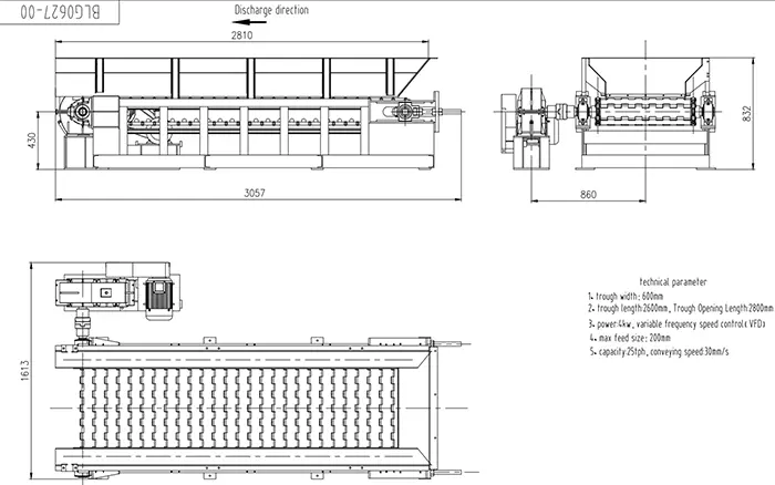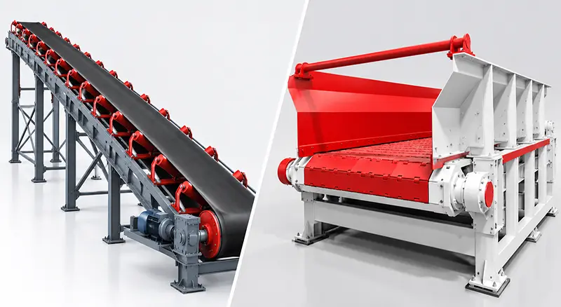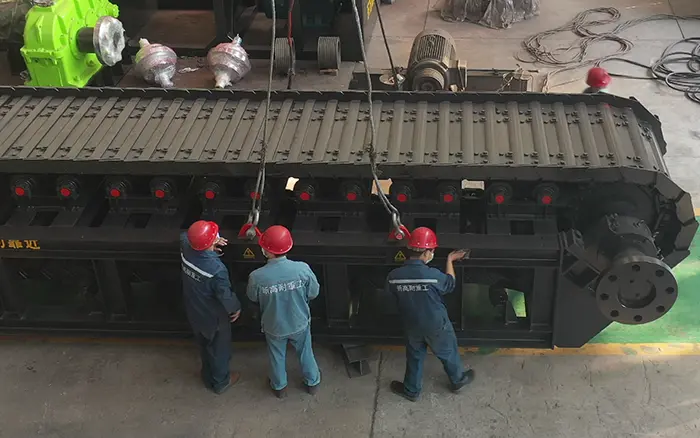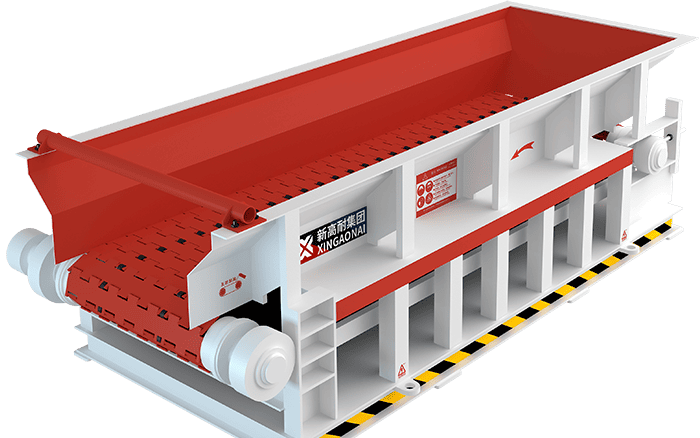
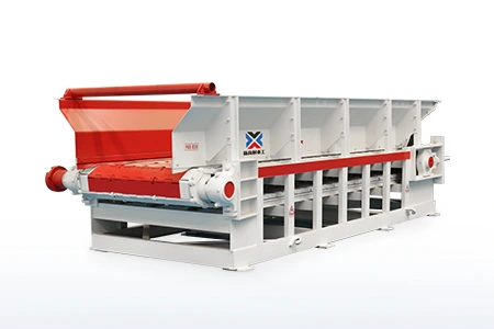
The apron feeder working principle is based on a low-speed, high-torque chain drive. A motor and reducer rotate the drive sprockets, which pull two parallel chains and the attached steel pans. Material resting on the pans is extracted from the hopper and carried toward the discharge point at a controlled rate.
Unlike a conventional conveyor that mainly transports material from one location to another, an apron feeder is designed to extract material from beneath a hopper or bin while supporting the pressure of the material above it.
The feeding rate is primarily controlled by:
Pan width
Material bed depth
Chain speed
Material bulk density
Hopper opening
Feeder inclination
Material flow characteristics
The current XINGAONAI BLG Series apron feeder has a published capacity range of 200–800 t/h and a maximum feed size of ≤500 mm, depending on the selected model.
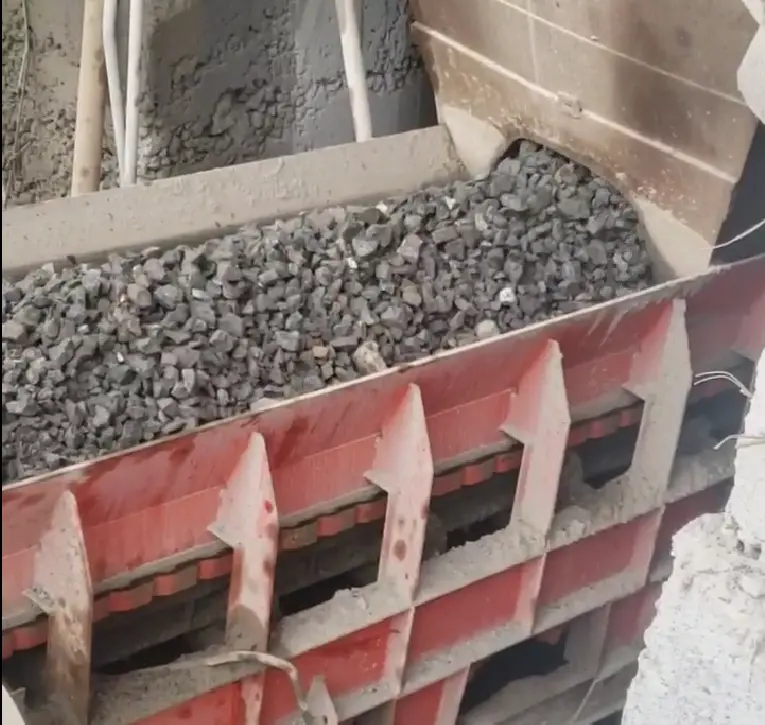
Apron Feeder Working Principle in One Diagram
A typical apron feeder transfers power and material through the following sequence:
Motor → Coupling → Reducer → Drive shaft → Sprockets → Chains → Apron pans → Material discharge
At the same time, the material follows this path:
Hopper → Loading zone → Carrying section → Discharge point → Downstream crusher or conveyor
After discharging the material, the empty pans travel around the drive or tail sprocket and return along the lower section of the feeder.
This continuous cycle allows the machine to maintain a controlled material flow as long as material remains available in the hopper.
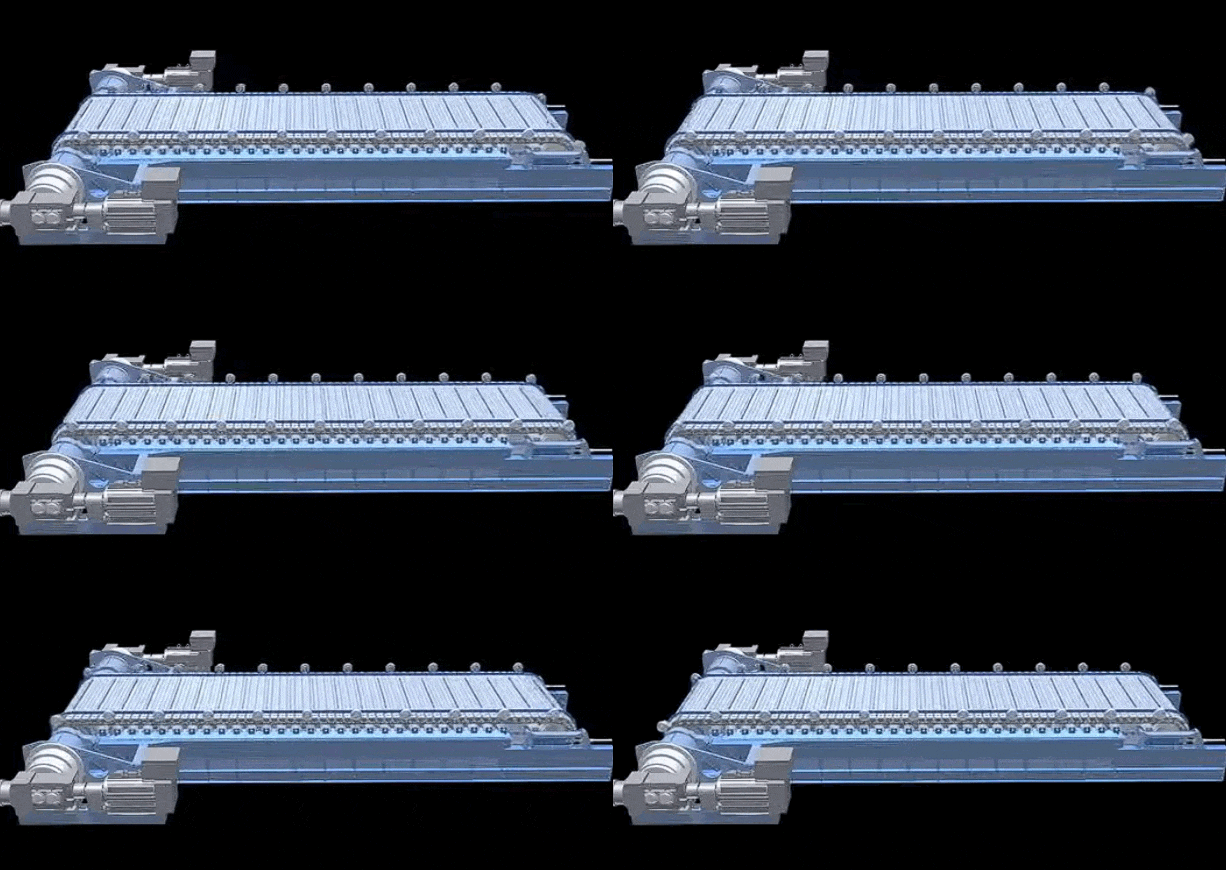
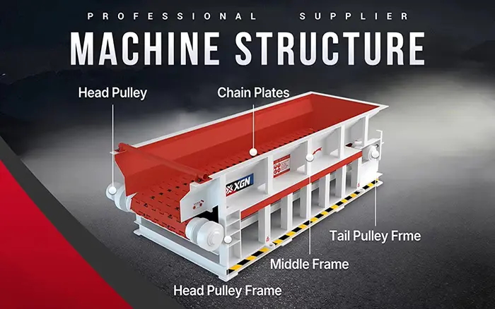
Main Components Involved in Apron Feeder Operation
Understanding the basic components makes the operating sequence easier to follow.
| Component | Function in the working process |
|---|---|
| Electric motor | Supplies rotational power |
| Coupling | Transfers power between the motor and reducer |
| Reducer | Converts motor speed into low-speed, high-torque output |
| Drive shaft | Transfers torque to the drive sprockets |
| Drive sprockets | Engage the chains and move the pan assembly |
| Chains | Pull the apron pans along the feeder |
| Apron pans | Support and carry the material |
| Support rollers | Carry the loaded pan-chain assembly |
| Return rollers or rails | Support the empty returning assembly |
| Tail shaft and sprockets | Guide the chains at the return end |
| Take-up system | Maintains the required chain adjustment |
| Frame | Supports and aligns the complete feeder |
| Skirt boards | Help contain material in the loading zone |
| VFD or speed controller | Adjusts chain speed and feed rate |
This article focuses on how these components work together. Their construction, wear points and replacement requirements are covered in the apron feeder parts and components guide.
Step-by-Step Apron Feeder Working Process
Step 1: Material Enters the Hopper
Bulk material is loaded into a hopper or bin above the apron feeder. Depending on the application, the material may arrive from:
Haul trucks
Wheel loaders
Excavators
Upstream conveyors
Stockpile reclaim systems
Processing equipment
The material rests on the apron pans through the hopper opening. The pans and supporting structure must carry both the moving material and the pressure created by the stored material above the feeder.
Large drop heights or direct truck dumping can create substantial impact. The loading arrangement should therefore be considered during feeder design.
Step 2: The Motor Starts the Drive System
When the feeder receives a start command, the electric motor begins rotating.
Because apron feeders operate at relatively low pan speed but require substantial pulling force, the motor does not normally drive the sprockets directly. Power passes through a reducer that decreases rotational speed and increases output torque.
The power path is:
The motor generates rotational power.
The coupling transfers power to the reducer.
The reducer decreases speed and increases torque.
The reducer output turns the drive shaft.
The drive shaft rotates the sprockets.
The sprockets engage and pull the chains.
The drive must provide enough torque to overcome friction, material pressure and the resistance encountered when starting under load.
Step 3: The Sprockets Pull the Chains
The drive sprockets engage with the chain links or chain components. As the sprockets rotate, they pull the chains along the feeder track.
The apron pans are connected to the chains, so the pans move at the same linear speed.
Correct sprocket and chain engagement is essential. Problems such as chain elongation, incorrect adjustment or sprocket wear can cause:
Impact during engagement
Uneven movement
Chain jumping
Increased vibration
Accelerated component wear
Misalignment of the pans
The chains should not be treated as ordinary conveyor chains. Their type, pitch, working load and maintenance requirements must match the feeder design.
Chain construction, wear measurement and replacement are explained in the apron feeder chain inspection and replacement guide.
Step 4: The Pans Extract Material from the Hopper
As the pan-chain assembly moves, the pans extract a layer of material from below the hopper opening.
This is a defining function of an apron feeder. The feeder does not simply receive loose material; it may operate beneath a substantial head of stored material.
The quantity extracted depends on:
Effective pan width
Material bed depth
Pan speed
Hopper opening
Material flow properties
Bulk density
Skirt boards along the loading zone help contain the material and establish the effective width of the moving bed.
The hopper opening and skirt arrangement must allow material to flow without creating excessive resistance or uncontrolled surging.
Step 5: The Loaded Pans Move Along the Carrying Section
The chains pull the loaded pans over support rollers or rails.
The support system carries:
Pan weight
Chain weight
Material load
Loading impact
Dynamic forces during operation
Correct roller spacing and alignment help distribute the load and reduce unnecessary resistance.
During the carrying stage, overlapping pans form a relatively continuous conveying surface. The overlap helps reduce material leakage between adjacent pans.
The pans must remain aligned with the chains and support system. Bent pans, loose fasteners or uneven loading can increase drag and create abnormal vibration.
Step 6: Feed Rate Is Controlled
The operating feed rate is normally adjusted by changing the chain speed through a variable-frequency drive.
When the chain speed increases, more material is delivered per unit of time. When the chain speed decreases, the feed rate is reduced.
However, chain speed is only one factor. Actual output also depends on:
Material bed depth
Pan width
Material bulk density
Hopper opening
Material consistency
Moisture and stickiness
Inclination
The feeder inclination is generally established during equipment design and installation. It should not be treated as a routine production-control setting.
A simplified capacity relationship can be expressed as:
Q = 3,600 × A × v × ρ × φ
Where:
Q = estimated capacity in tonnes per hour
A = effective material cross-sectional area in square metres
v = pan speed in metres per second
ρ = material bulk density in tonnes per cubic metre
φ = correction factor for filling and material conditions
This equation provides an initial estimate. Final capacity and drive selection must account for hopper loads, starting resistance, inclination, material behavior and mechanical efficiency.
Refer to the apron feeder design and sizing guide for a more detailed explanation of capacity, width and power calculations.
Step 7: Material Discharges into Downstream Equipment
At the discharge end, the material leaves the pans as they travel around the end section of the feeder.
The apron feeder may discharge into:
Jaw crusher
Gyratory crusher
Impact crusher
Conveyor
Vibrating screen
Grinding or processing system
Intermediate transfer chute
The discharge chute should guide the material without causing excessive buildup or impact on downstream equipment.
Stable discharge is one of the main purposes of the apron feeder. Instead of allowing an uncontrolled mass of material to enter the crusher, the feeder regulates the flow according to the downstream equipment’s capacity.
Step 8: Empty Pans Return to the Loading End
After the material is discharged, the empty pans continue around the sprocket and move back along the lower return section.
The tail sprockets guide the chain assembly back toward the loading end. A take-up or adjustment system helps maintain the required chain condition.
The complete operating cycle is therefore:
Load material onto the pans.
Pull the loaded pans forward.
Discharge material.
Return the empty pans.
Reload the pans.
Repeat continuously.
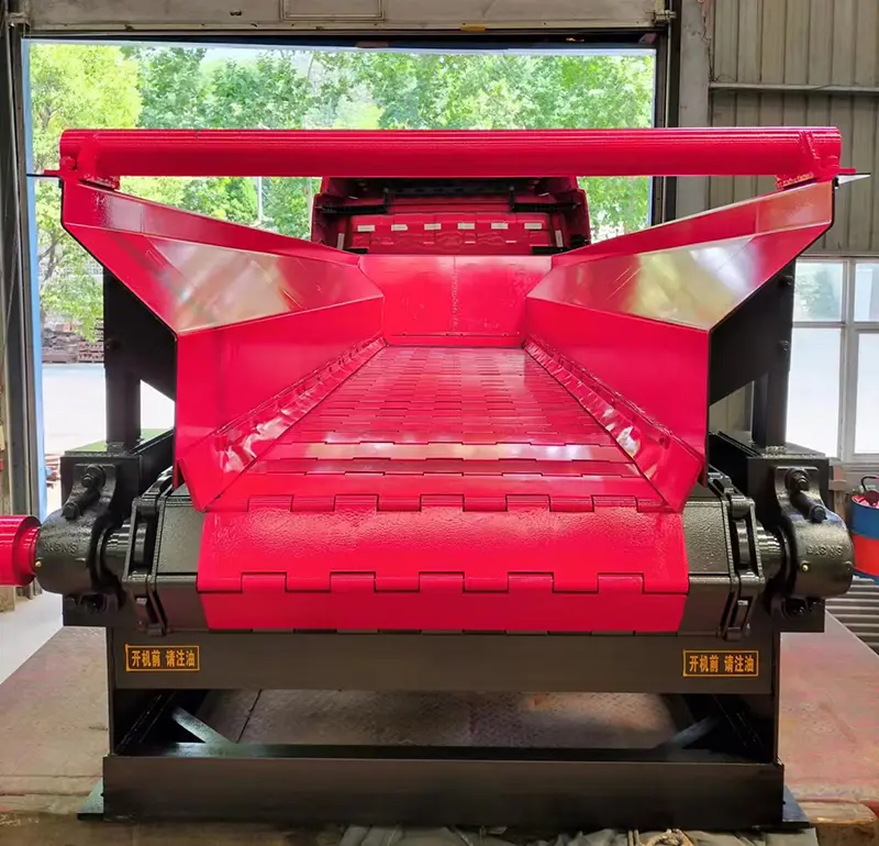
How an Apron Feeder Controls Material Flow
The apron feeder does not normally meter material by weighing each individual load. Instead, it controls the volume of material extracted from the hopper.
The main control variables are:
Chain Speed
A VFD changes motor speed, which changes the reducer output and pan-chain travel speed.
Speed adjustment should remain within the limits specified for the drive, chains and feeder structure.
Material Bed Depth
The depth of material on the pans affects the cross-sectional area being conveyed. Bed depth is influenced by hopper opening, gate position and skirt-board arrangement.
Effective Loading Width
The usable width between the skirt boards determines how much material can be carried across the feeder.
Material Bulk Density
The same volumetric flow can represent very different tonnage when material density changes.
For example, a feeder carrying low-density coal will deliver fewer tonnes per hour than the same feeder carrying dense ore at an identical bed depth and speed.
Downstream Demand
The feeder may be linked to the crusher, conveyor or process-control system.
A control system can reduce feeder speed when:
Crusher motor current increases
A downstream bin reaches a high level
A conveyor approaches its capacity
A process controller requests a lower flow rate
It can increase speed when downstream capacity becomes available.
Starting an Apron Feeder Under Load
An apron feeder is often installed beneath a hopper that remains partially or completely loaded. The drive system must therefore be designed for the required starting torque.
Starting resistance may increase because of:
Material pressure
Compacted feed
Sticky material
Cold lubricant
Misalignment
Excessive chain adjustment
Damaged rollers
Material trapped around moving parts
The manufacturer should evaluate starting conditions during drive selection. Motor power alone does not describe the available starting torque at the sprocket.
Before starting a loaded feeder, operators should confirm that:
The discharge path is clear
Downstream equipment is running
No maintenance personnel are inside the guarded area
Guards and access covers are installed
Emergency-stop circuits are available
The drive and bearings are ready for operation
No obvious material blockage is present
Recommended Startup Sequence
A typical production-line startup sequence is:
Inspect the feeder and surrounding area.
Start the downstream discharge conveyor or processing equipment.
Start the crusher or receiving equipment.
Start the apron feeder at a low controlled speed.
Confirm smooth chain and pan movement.
Increase the feed rate gradually.
Monitor current, noise, vibration and material flow.
Starting downstream equipment first ensures that discharged material has somewhere to go.
The exact sequence must follow the site’s operating procedure and interlock logic.
Recommended Shutdown Sequence
A typical controlled shutdown is:
Stop or reduce material entering the hopper where possible.
Reduce the apron feeder speed.
Allow the feeder to discharge the remaining moving material.
Stop the apron feeder.
Stop the downstream equipment after its material has cleared.
Isolate the equipment if inspection or maintenance is required.
Emergency shutdowns may leave material on the feeder. Before restarting, operators should check for blockage, damage and excessive starting load.
How Apron Feeder Operation Changes with Material Conditions
Large and Angular Material
Large, sharp material increases impact on the pans and loading zone. Pan strength, drop height and support arrangement become especially important.
Abrasive Material
Abrasive ore increases wear on pans, liners, chains and sprockets. Wear should be measured rather than estimated only from operating hours.
Wet or Sticky Material
Sticky material may adhere to:
Pans
Skirt boards
Hopper walls
Discharge chutes
Return section
Material buildup increases resistance and may reduce the effective carrying area.
Fine Material
Fine particles may enter gaps, bearings or chain contact areas. Sealing, cleaning and dust control become important.
Variable Bulk Density
When the feed density changes, tonnage also changes even if pan speed and bed depth remain constant. A control system using motor load, belt scales or other instrumentation may be required where accurate tonnage control is important.
Common Apron Feeder Operating Problems
| Symptom | Possible working-principle-related cause |
|---|---|
| Feeder does not start | Excessive hopper load, blockage, drive fault or seized component |
| Capacity is too low | Low chain speed, insufficient bed depth or restricted hopper opening |
| Capacity fluctuates | Inconsistent hopper flow, bridging or variable material density |
| Pans move unevenly | Chain, sprocket, roller or alignment problem |
| Chain impacts sprockets | Chain elongation, incorrect adjustment or worn sprocket teeth |
| Feeder pulls to one side | Uneven loading, misalignment or unequal chain condition |
| Motor current is high | Excessive load, mechanical resistance or material buildup |
| Material spills from the sides | Incorrect skirt adjustment, excessive bed depth or uneven loading |
| Abnormal noise | Loose pans, damaged rollers, worn chain or foreign material |
| Discharge blockage | Chute restriction, sticky material or downstream stoppage |
The feeder should be stopped if abnormal movement, severe impact, chain jumping or structural damage is observed.
Always isolate and lock out the machine before entering the guarded area or inspecting moving components.
Apron Feeder vs. Belt Feeder Working Principle
Both machines provide controlled feeding, but their carrying systems are different.
| Feature | Apron feeder | Belt feeder |
|---|---|---|
| Carrying surface | Overlapping steel pans | Flexible rubber or reinforced belt |
| Drive transmission | Sprockets and chains | Drive pulley and belt friction |
| Operating speed | Generally lower | Generally higher |
| Impact resistance | Suitable for heavier impact | More limited by belt construction |
| Abrasive material | Suitable with correct component design | May accelerate belt wear |
| Material extraction | Suitable beneath heavy hopper loads | Suitable for controlled, lighter-duty extraction |
| Maintenance focus | Chains, pans, sprockets and rollers | Belt, pulleys, idlers and tracking |
See the belt feeder vs apron feeder comparison for equipment-selection guidance.
Conclusion
The apron feeder working principle combines low-speed, high-torque power transmission with a chain-driven steel pan assembly.
The motor supplies power to the reducer, the reducer turns the drive shaft and sprockets, and the sprockets pull the chains and pans. Material is extracted from beneath the hopper, carried along the loaded section and discharged into downstream equipment. The empty pans then return along the lower section to repeat the cycle.
Feed rate is mainly controlled through chain speed, pan width and material bed depth. Material density, hopper design, inclination and flow characteristics also affect actual capacity.
Correct operation depends on more than the working mechanism itself. Drive torque, hopper loading, chain condition, sprocket engagement, roller alignment and discharge conditions must all be considered to maintain stable feeding.