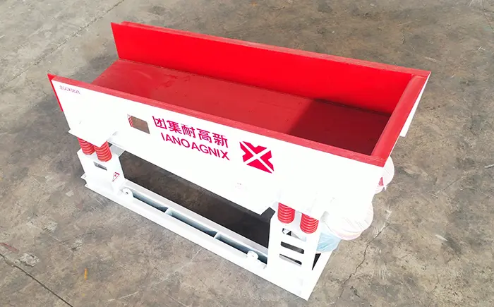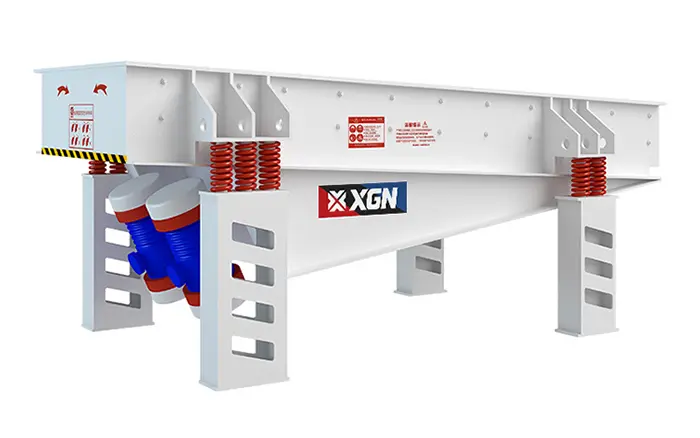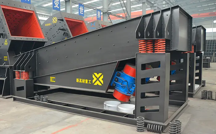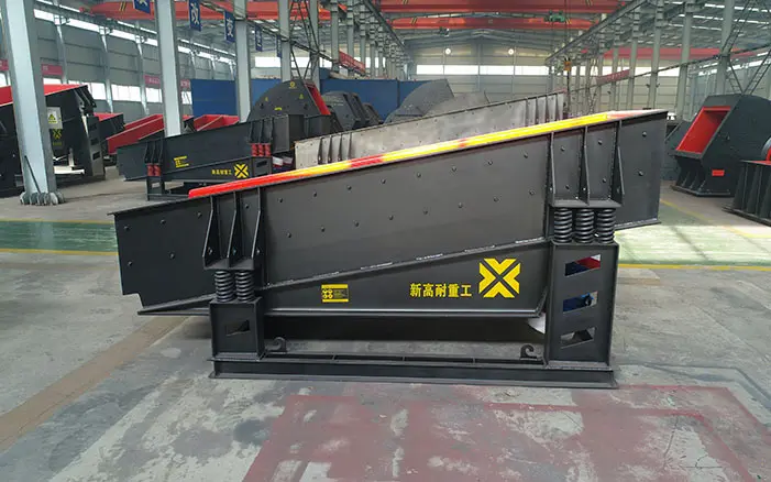
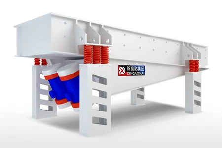
A linear vibrating feeder uses controlled vibration along a fixed direction to move bulk material through a feeding trough.
In a common dual-motor arrangement, two vibration motors rotate in opposite directions. Their force components cancel across the unwanted direction and combine along the selected vibration line. The resulting reciprocating motion causes the material to advance through a sequence of short lifting, sliding and forward-landing movements.
The word “linear” describes the vibration trajectory. It does not automatically identify the feeder’s capacity, material range or industrial application.
A linear feeder can still perform poorly if:
The motors rotate in the wrong directions
Excitation settings are unequal
Springs have different stiffness or compression
The trough contacts a fixed structure
Material loads one side of the feeder
The support frame is not sufficiently rigid
The hopper applies excessive pressure to the trough
This guide concentrates on how linear motion is generated, how the motion affects material flow and how to identify abnormal feeder movement during commissioning and operation.
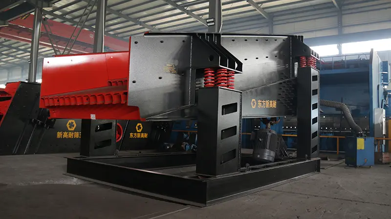
What Does “Linear” Mean in a Vibrating Feeder?
In this context, linear means that the feeder trough moves back and forth along a substantially straight vibration line.
The vibration direction is normally inclined relative to the trough surface. This angled motion provides both:
A component that lifts or reduces the contact between the material and trough
A component that advances the material toward the discharge end
The material does not necessarily remain airborne throughout the process. Depending on the vibration settings and material properties, particles may:
Slide along the trough
Make very short forward hops
Roll or rotate
Form a moving material bed
Alternate between contact and micro-flight
The actual material trajectory depends on the interaction between the feeder motion and material properties.
For a general introduction to the equipment, see what is a vibrating feeder. This article addresses the more specific linear-motion configuration.
How Two Counter-Rotating Motors Produce Linear Motion
A common linear feeder uses two unbalanced vibration motors mounted symmetrically on the feeder body.
Each motor contains eccentric weights. As the motor shaft rotates, the eccentric mass generates centrifugal force.
The approximate force generated by an eccentric rotating mass is related to:
F = m × e × ω²
Where:
F is the centrifugal force
m is the eccentric mass
e is the eccentric distance from the shaft center
ω is the angular speed
Because angular speed is squared, changes in motor speed can have a substantial effect on the generated force. Motor-speed adjustment should therefore remain within the approved operating range.
When the two motors rotate at the same speed in opposite directions:
Force components perpendicular to the intended vibration line oppose each other
These unwanted components substantially cancel
Force components along the intended direction combine
The combined force reverses direction repeatedly
The trough vibrates along a fixed line
The resulting motion is only stable when the two sides of the system work together correctly.
Why the Motors Must Rotate in Opposite Directions
If two motors intended for linear excitation rotate in the same direction, the force components do not combine in the required way.
The feeder may then exhibit:
Circular or elliptical movement
Excessive lateral vibration
Trough twisting
Unequal amplitude
Unstable material flow
Higher structural stress
Accelerated spring and fastener wear
Correct motor rotation must be verified during commissioning.
The required rotation should be confirmed from the equipment drawing, motor markings and manufacturer instructions. It should not be assumed from motor position alone.
If one motor stops while the other continues running, the feeder should be stopped according to the approved shutdown procedure. Continued single-motor operation can create severe unbalanced vibration and structural loading.
How Material Moves Along the Trough
Material movement is created by the relationship between trough acceleration, gravity, friction and the vibration direction.
A simplified feeding cycle includes the following stages.
1. Trough Acceleration
The vibrating body accelerates along its selected motion line.
The vertical component changes the effective contact force between the material and trough, while the forward component contributes to material travel.
2. Reduced Contact or Lifting
When the vibration acceleration is sufficient, the material’s contact with the trough is reduced. Some particles may enter a short micro-flight.
3. Forward Movement
Because of inertia and the angled vibration direction, the material moves slightly toward the discharge end.
4. Landing or Renewed Contact
The material contacts the trough again at a position slightly farther forward.
5. Repeated Conveying Cycle
The cycle repeats many times per minute, creating a continuous material flow.
The detailed movement is affected by:
Particle size
Particle shape
Bulk density
Moisture
Surface friction
Material bed depth
Vibration amplitude
Vibration frequency
Vibration direction angle
Trough inclination
Linear Motion vs. Circular and Elliptical Motion
Not every vibrating feeder uses an identical motion path.
| Motion trajectory | General characteristic | Possible effect on material |
|---|---|---|
| Linear | Movement concentrated along a fixed vibration line | Directional and comparatively controlled forward feeding |
| Circular | Trough moves around a circular path | Greater rolling and agitation of the material bed |
| Elliptical | Combined horizontal and vertical movement of different magnitudes | Balance between material agitation and forward travel |
The appropriate motion depends on the feeder design and process requirement.
Linear motion can be beneficial when:
A defined material-flow direction is required
The feeder uses two counter-rotating vibration motors
Material should be distributed steadily to downstream equipment
Side-to-side movement must be limited
The trough needs a predictable directional stroke
Circular or elliptical motion is not automatically inferior. A different trajectory may be appropriate for another feeder design or material condition.
The equipment manufacturer should specify the intended motion rather than allowing the operator to judge the design only from visual observation.
Parameters That Control Linear Feeder Performance
Vibration Amplitude
Amplitude describes the extent of the trough’s movement during each vibration cycle.
Increasing amplitude may increase material movement, but higher amplitude is not automatically better.
Excessive amplitude may cause:
Material spillage
Excessive impact between material and trough
Unstable bed depth
Increased dynamic structural loads
Faster wear
Loosened fasteners
Damage to springs or connected chutes
Insufficient amplitude may cause slow movement, material accumulation or reduced capacity.
Amplitude should be checked at multiple points on the feeder rather than at only one location.
Vibration Frequency
Frequency describes how many vibration cycles occur within a given time.
Frequency affects:
Number of material movements per second
Material response
Feed stability
Dynamic force
Motor behavior
Structural response
Frequency and amplitude must be considered together. A high frequency with unsuitable amplitude may not produce the required material movement.
Vibration Direction Angle
The vibration direction angle determines how the excitation force is divided between lifting and forward movement.
A direction with a greater vertical component may increase material lifting but does not necessarily provide the highest forward capacity.
A direction with insufficient vertical action may allow material to remain in excessive contact with the trough, increasing sliding resistance.
The correct angle depends on the feeder geometry and material.
Trough Inclination
A downward inclination may assist material movement, while a horizontal or upward arrangement may require different vibration settings.
The permitted installation angle should be confirmed by the manufacturer.
Material Bed Depth
A deeper bed increases the load carried by the feeder and changes the way vibration is transmitted through the material.
Excessive bed depth may:
Reduce forward movement
Increase motor current
Restrict vibration
Cause unstable discharge
Hide differences in left-to-right material distribution
Surface Friction
Liner condition, material moisture and surface buildup affect the friction between the material and trough.
The same vibration settings may produce different feeding rates after liners become worn or material moisture changes.
Why Higher Amplitude Does Not Always Increase Capacity
Increasing amplitude may appear to be a simple way to increase feed rate. However, feeder capacity is controlled by several interacting factors.
Capacity may remain low despite higher amplitude when:
The hopper outlet restricts material flow
Wet material adheres to the trough
The material bed is too deep
The vibration direction is unsuitable
One motor produces less force than the other
Springs restrict normal movement
The feeder contacts surrounding steelwork
The discharge chute creates a blockage
Increasing excitation without identifying the restriction may increase equipment stress without improving production.
Feed-rate adjustment should therefore be based on operating measurements rather than visual movement alone.
Dual-Motor Synchronization Requirements
Stable linear movement requires both motors to produce a coordinated excitation force.
Important conditions include:
Matching Motor Speed
The motors must operate at the specified speed. A significant difference can cause unstable force combination.
Opposite Rotation
The motors must rotate in the intended opposite directions.
Equal Excitation Settings
When adjustable eccentric weights are used, corresponding settings should be equal unless the equipment manufacturer specifies another arrangement.
Both ends of each vibration motor should be adjusted according to the approved procedure.
Symmetrical Installation
Motor mounting position and angle affect the resultant vibration direction.
Loose, deformed or incorrectly positioned motor bases can change the force transmitted to the trough.
Stable Electrical Supply
Voltage imbalance, phase problems or poor connections can affect motor current and performance.
Rigid Motor Mounting
Mounting bolts and contact surfaces must transmit the excitation force without movement between the motor and mounting plate.
Detailed motor construction and selection considerations are covered in the vibrating feeder motor article.
How to Check Whether the Motion Is Truly Linear
Visual inspection provides useful clues, but measurement is more reliable.
A practical commissioning check should compare the feeder at several locations.
Recommended measurement points include:
Front left
Front right
Rear left
Rear right
Check the following at each point:
Amplitude
Motion direction
Lateral movement
Structural response
Material bed behavior
Also record:
Current of motor A
Current of motor B
Motor surface temperature
Motor rotation direction
No-load behavior
Loaded behavior
Feed rate
Material distribution
Amplitude cards, approved vibration instruments or stroboscopic measurement may be used according to site procedures.
Measurements should be taken from safe observation locations. The equipment must be isolated before anyone physically inspects motors, springs, fasteners or structural connections.
What Causes Sideways Movement?
A correctly operating linear feeder should not exhibit severe uncontrolled lateral movement.
Possible causes include:
Incorrect motor rotation
Unequal eccentric-weight settings
One motor producing less excitation force
Loose motor mounting bolts
Different spring stiffness on the two sides
Broken or permanently compressed springs
Material concentrated on one side
Trough or frame deformation
Feeder contact with a fixed structure
Uneven supporting structure
Material buildup on one side
Cracking around a structural connection
Sideways movement should not be corrected by changing one motor setting without first identifying the cause.
An arbitrary adjustment may temporarily reduce visible motion while increasing internal structural stress.
Why Amplitude May Differ Between the Front and Rear
A small measured difference may be influenced by design and loading, but a large or changing difference requires investigation.
Possible causes include:
Uneven material distribution
Different spring compression
Damaged springs
Loose fasteners
Trough deformation
Material buildup
Cracks in the feeder body
Incorrect motor position
Connection with a rigid chute or dust cover
Flexible supporting steelwork
Uneven hopper pressure
Compare both no-load and loaded measurements.
If the feeder appears normal while empty but develops unequal amplitude under load, the hopper interface or material distribution may be contributing to the problem.
Linear Vibrating Feeder vs. Linear Vibrating Screen
A feeder and a screen may both use linear vibration, but they have different process functions.
| Comparison | Linear vibrating feeder | Linear vibrating screen |
|---|---|---|
| Primary function | Control and transport material flow | Separate material by particle size |
| Main surface | Solid trough or partial grizzly section | Screen media with defined apertures |
| Normal product streams | Usually one main discharge | Oversize and undersize products |
| Main performance measure | Stable feed rate | Screening capacity and separation efficiency |
| Typical installation | Under a hopper or before equipment | After crushing, grinding or washing |
| Main control issue | Amplitude, feed rate and material distribution | Deck loading, aperture condition and screening efficiency |
A feeder can include a short grizzly section for preliminary fines removal. However, this does not make it equivalent to a full screening machine.
More information about the feeding and pre-screening combination is available in the guide to a vibrating feeder with a screening section.
When Is Linear Motion Suitable?
A linear-motion feeder may be suitable when the project requires:
Short-distance material feeding
Controlled forward movement
Continuous crusher feeding
Stable transfer from a hopper
Even distribution across a downstream inlet
Motor-driven heavy-duty operation
Adjustable production rate
Limited lateral movement
It may be installed ahead of:
Jaw crushers
Impact crushers
Cone crushers
Vibrating screens
Belt conveyors
Grinding equipment
Other compatible processing machinery
For detailed selection based on ore, rock, hopper loading and primary-crushing conditions, refer to the mining vibrating feeder selection guide.
That page addresses application selection, while this article focuses on the linear vibration system itself.
When a Linear Vibrating Feeder May Not Be Suitable
Another feeding method may be required when:
The transfer distance is long
Exact gravimetric dosing is required without a weighing system
Material is extremely sticky or cohesive
Very large rocks create severe direct impact
The hopper applies an excessive static head load
The material condition prevents reliable vibratory movement
The supporting structure cannot accommodate dynamic loads
The process requires a different motion trajectory
These conditions should be identified before equipment selection.
Commissioning Checks for Linear Motion
Before Startup
Verify:
Both motors match the specified type
Motor installation positions are correct
Eccentric settings are approved and equal
Electrical connections are complete
Rotation markings are available
Springs are correctly installed
Temporary shipping restraints are removed
The trough has sufficient clearance
Flexible connections do not restrict movement
Fasteners are tightened
Guards are installed
Emergency stops and interlocks operate correctly
No-Load Test
Check:
Motor rotation direction
Linear motion direction
Left-to-right amplitude
Front-to-rear amplitude
Motor current
Motor temperature
Spring movement
Abnormal sound
Contact with surrounding equipment
Supporting-structure vibration
Loaded Test
Introduce material gradually and check:
Material travel direction
Feed-rate stability
Material bed depth
Left-to-right distribution
Motor current
Motor temperature
Sideways movement
Discharge trajectory
Material buildup
Downstream equipment loading
A feeder should not be accepted based only on a no-load test. Material load can reveal problems that are not visible while the trough is empty.
Linear-Motion Troubleshooting Table
| Observed condition | Possible causes | Recommended initial checks |
|---|---|---|
| Feeder moves sideways | Incorrect motor rotation, unequal excitation, damaged springs or uneven loading | Check motor directions, settings, spring condition and material distribution |
| Material drifts to one side | Trough not level, one-sided loading or unequal amplitude | Check installation level, hopper discharge and four-point amplitude |
| One motor draws higher current | Unequal load, electrical imbalance, mounting problem or motor fault | Compare voltage, current, settings and mechanical mounting |
| Front amplitude differs greatly from rear | Spring problem, buildup, structural contact or frame flexibility | Inspect springs, clearance, trough and supporting structure |
| Low feed rate despite strong vibration | Restricted hopper outlet, unsuitable direction angle or sticky material | Inspect material flow and hopper-feeder interface |
| Excessive material jumping | Excessive amplitude, unsuitable frequency or shallow material bed | Verify approved settings and feed conditions |
| Bolts repeatedly loosen | Excessive dynamic force, poor joint contact or abnormal motion | Inspect movement pattern, mounting surfaces and tightening method |
| Feeder becomes noisy | Loose parts, bearing wear, structural contact or cracking | Stop safely and inspect before returning to service |
| Motors fail to synchronize | Incorrect electrical supply, unequal settings or mechanical restriction | Check power supply, motor specifications and feeder clearance |
| Stable when empty but unstable when loaded | Uneven hopper pressure, excessive bed depth or one-sided material flow | Check hopper opening, gate position and loaded amplitude |
These checks help identify the investigation area. They should not be treated as a final diagnosis without inspecting the complete feeder system.
How XINGAONAI Configures Vibrating Feeders
XINGAONAI’s current ZG Series Vibrating Feeder range includes models for different feed sizes and production capacities.
Depending on the model and configuration, the feeder may use a dual-motor excitation system or another approved drive arrangement to generate the required motion.
The drive system should be confirmed according to:
Material type
Maximum feed size
Required capacity
Bulk density
Moisture and clay content
Trough dimensions
Installation angle
Hopper outlet
Material drop height
Downstream machine
Required vibration trajectory
Available power supply
The full product model table should remain on the product page. This linear-motion guide is intended to help users understand drive behavior, commissioning and troubleshooting rather than duplicate the commercial specification table.
Information Required for a Linear-Motion Review
When requesting a new feeder or investigating an existing unit, prepare:
Feeder manufacturer and model
Trough dimensions
Material name
Maximum feed size
Bulk density
Moisture content
Normal and maximum feed rate
Motor models
Motor power
Rated motor speed
Eccentric-weight settings
Motor mounting angles
Rotation directions
Recorded motor currents
Front-left amplitude
Front-right amplitude
Rear-left amplitude
Rear-right amplitude
Spring dimensions and condition
Hopper outlet dimensions
Material bed depth
Installation angle
Photographs of the complete installation
Video of operation taken from a safe position
Description of when the problem began
Conclusion
A linear vibrating feeder depends on the controlled interaction of two motors, the feeder body, springs, supporting structure and material load.
In a dual-motor system, opposite rotation allows the excitation forces to combine along the intended direction and cancel across the unwanted direction. When motor settings, supports or loading become unequal, the feeder may develop lateral motion, unequal amplitude and unstable material flow.
Reliable operation requires:
Correct motor rotation
Matching excitation settings
Stable synchronization
Symmetrical mounting
Springs in consistent condition
Adequate vibration clearance
A rigid supporting structure
Even material loading
Verification under both empty and loaded conditions
Understanding these linear-motion characteristics helps operators distinguish a normal material response from an actual mechanical or electrical problem.