Selecting a vibrating feeder motor requires more than matching the power shown on its nameplate. Two motors with the same kilowatt rating may have different speeds, excitation forces, mounting dimensions, operating currents and bearing arrangements.
An unsuitable replacement can change feeder motion, overload the mounting structure or create repeated electrical and mechanical problems.
The first step is to identify how the feeder generates vibration. Some feeders use motors with built-in eccentric weights. Others use a conventional electric motor to power a separate mechanical exciter. Electromagnetic feeders use another drive arrangement entirely.
This guide explains how to identify the installed drive, compare motor specifications, check replacement compatibility and recognize common motor-related faults.
For the complete material-conveying process, refer to the vibrating feeder working principle.
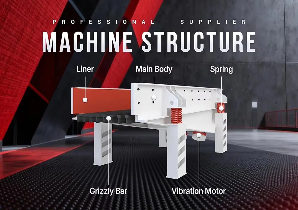
Identify the Drive Before Ordering a Motor
The phrase “vibrating feeder motor” can describe different components. Confirm the drive arrangement before selecting a replacement.
| Drive arrangement | What the motor does | Main replacement considerations |
|---|---|---|
| Direct-mounted vibration motor | Rotates eccentric weights to generate excitation | Excitation force, speed, power, weight setting, mass and mounting dimensions |
| Conventional motor with separate exciter | Supplies rotational power to an external vibration-generating mechanism | Power, speed, torque characteristics, shaft, transmission and exciter compatibility |
| Electromagnetic drive | Uses controlled magnetic force to excite the moving assembly | Coil, controller, electrical supply and complete drive compatibility |
A conventional motor and a vibration motor are not interchangeable simply because their power ratings match.
For an electromagnetic feeder, a fault described as a “motor problem” may actually involve the coil, controller, wiring or drive adjustment. Identify the installed components before requesting spare parts.
What Makes a Vibration Motor Different?
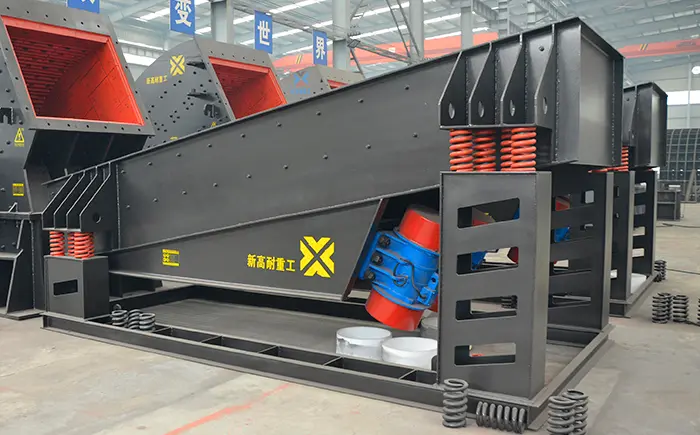
A vibration motor incorporates rotating unbalanced masses, commonly beneath protective covers at the shaft ends.
As these masses rotate, they generate a changing excitation force. The motor housing and mounting feet transmit that force into the feeder structure.
The motor therefore performs two connected functions:
Converting electrical energy into shaft rotation;
Generating mechanical excitation through the rotating unbalance.
Its bearings, shaft, housing and mounting arrangement must withstand the resulting loads.
A conventional motor driving a separate exciter performs the first function, while the exciter performs the second. This distinction changes how the equipment should be inspected and specified.
Motor Specifications That Must Be Checked
1. Complete Model and Serial Number
Record the full designation, including suffixes, voltage codes and any special execution markings.
Similar model names do not prove interchangeability. A suffix may identify a different mounting arrangement, electrical configuration, bearing design or operating condition.
Photograph the complete nameplate rather than relying on a handwritten abbreviation.
2. Rated Excitation Force
For a vibration motor, excitation force is a central selection value.
Confirm:
The stated force and its unit;
The speed at which it is rated;
Whether the figure represents the maximum setting;
The actual installed weight setting;
Whether the feeder specification refers to one motor or the complete drive arrangement.
Do not confuse maximum nameplate force with the force currently used on the machine.
Increasing excitation beyond the approved configuration can raise dynamic loads on the trough, motor base, fasteners and supporting components.
3. Rated Speed and Supply Frequency
Speed affects the frequency of excitation and the response of the complete feeder.
Two motors with the same power but different rated speeds can produce substantially different operating behavior.
Confirm the required supply frequency and rated speed together. A motor should not be transferred between different electrical supplies without checking its rating and the feeder’s approved operating conditions.
4. Rated Power and Current
Power describes the motor’s electrical-to-mechanical capability, but it does not independently determine feeder capacity.
Check the rated current for the actual voltage and connection arrangement. Protection settings must suit the installed motor and the applicable electrical design.
For a two-motor feeder, document each motor separately. A nameplate reading of “2 × 5.5 kW” describes two motors rather than one 11 kW replacement.
5. Voltage, Phase and Connection
Verify:
Supply voltage;
Number of phases;
Supply frequency;
Permitted connection arrangement;
Terminal diagram;
Starting method;
Control-system compatibility.
Do not assume that a replacement can use the previous terminal links or wiring arrangement.
Electrical connection and testing should be performed by qualified personnel using the motor documentation.
6. Mounting Dimensions and Motor Mass
Compare more than the overall motor size.
Important dimensions include:
Mounting-hole centres;
Bolt-hole diameter;
Foot thickness;
Mounting-surface geometry;
Overall envelope;
Weight-cover clearance;
Cable-entry position;
Maintenance access.
Motor mass also matters because it becomes part of the feeder’s vibrating assembly.
A replacement that fits the bolt holes may still change the system response if its mass or excitation characteristics differ.
7. Duty and Environmental Requirements
Check compatibility with the actual installation:
Continuous or intermittent operation;
Ambient temperature;
Altitude;
Dust exposure;
Water exposure;
Corrosive conditions;
Thermal protection;
Insulation requirements;
Hazardous-area requirements, where applicable.
An enclosure protection rating does not, by itself, establish suitability for an explosive atmosphere.
Why Matching Kilowatts Alone Is Not Enough
Consider two replacement candidates with the same power rating.
One may operate at a different speed, generate a different excitation force or have a heavier housing. Even if both start successfully, their effects on the feeder can differ.
A replacement must match the equipment as a system:
| Compatibility area | Why it matters |
|---|---|
| Excitation force and setting | Determines the applied dynamic excitation |
| Operating speed | Affects excitation frequency and system response |
| Motor mass | Changes the vibrating assembly |
| Mounting geometry | Determines how loads enter the structure |
| Electrical characteristics | Affects starting, protection and operating current |
| Bearing and duty arrangement | Influences suitability for continuous vibration |
| Paired-drive compatibility | Affects coordinated operation where two motors are used |
A larger motor is therefore not automatically an upgrade.
If the feeder is undersized for the material or hopper load, changing the motor may leave the underlying capacity problem unresolved. Use the mining vibrating feeder selection guide to evaluate the complete duty.
Replacing One Motor on a Two-Motor Feeder
Where a feeder uses two vibration motors, the replacement must be compatible with both the feeder and the remaining motor.
Check:
Rated speed;
Excitation-force range;
Actual weight setting;
Electrical ratings;
Motor mass;
Mounting arrangement;
Manufacturer-approved pairing requirements.
Replacing only one motor may be appropriate when a compatible unit is available and the remaining motor is in acceptable condition. It should not be assumed that any motor with the same power can operate as a matched partner.
Inspect the surviving motor for bearing condition, mounting damage, electrical problems and signs of the same failure mechanism.
The force combination, rotation relationship and motion checks belong to the linear vibrating feeder guide.
Installation Checks That Protect the Motor and Feeder
A correctly specified motor can still fail prematurely if its mounting or electrical installation is unsuitable.
Before mechanical inspection or installation, stop and isolate the feeder under the site’s approved procedure. Secure against unexpected startup and allow hot components to cool.
Mounting Surface
The motor feet should seat against the intended mounting surface without rocking.
Inspect for:
Cracks;
Fretting marks;
Deformation;
Elongated bolt holes;
Damaged threads;
Loose mounting plates;
Debris preventing full contact.
Do not pull a distorted mounting surface into position by tightening the motor bolts.
Fasteners
Use the specified fastener grade, arrangement, tightening sequence and torque.
Repeated loosening requires investigation of the joint, mounting stiffness and operating loads. Replacing a loose bolt without correcting its cause can allow the problem to return.
Cable Routing
Cables must accommodate the machine’s designed movement without rubbing, stretching or carrying the mechanical load.
Check cable glands, strain relief, protective earthing and terminal-box sealing.
Keep cables away from hot surfaces, sharp edges, material impact and moving components.
Covers and Access
Eccentric-weight covers and terminal-box covers must be correctly fitted before operation.
Confirm sufficient clearance around the covers and access for future inspection without interference from chutes, guards or the feeder structure.
Eccentric-Weight Adjustment: Confirm the Setting Before Changing It
On adjustable vibration motors, the relationship between fixed and adjustable weights controls the effective unbalance.
Before changing a setting:
Identify the exact motor model;
Obtain its adjustment instructions;
Record the existing settings;
Confirm the feeder’s approved excitation;
Stop and isolate the equipment;
Follow the required arrangement at both shaft ends;
Tighten and secure the weights as specified;
Refit all covers before operation.
Weight scales and adjustment procedures differ between motor designs. A percentage marked on one motor should not be treated as a universal force value.
For paired drives, verify the required settings across both motors.
Changing the weight setting changes excitation; the resulting trough displacement also depends on the feeder’s mass, springs, loading and operating speed.
Can a Vibrating Feeder Motor Use a VFD?
Some vibration motors and feeder systems permit variable-frequency operation. Compatibility must be confirmed for the complete installation.
Check:
Motor manufacturer’s permitted frequency range;
Feeder manufacturer’s permitted speed range;
Excitation-force limits;
Motor cooling at reduced speed;
Required drive-control characteristics;
Starting and stopping behavior;
Thermal protection;
Electrical insulation requirements;
Paired-motor control arrangement.
The motor’s permitted range and the feeder’s permitted range may differ.
A VFD should not be used to overcome poor feeding by increasing speed beyond the approved operating conditions. Changes in speed can alter excitation and bring the machine closer to an undesirable dynamic response.
Common Vibrating Feeder Motor Problems
The following checks help identify a direction for investigation. They do not replace electrical testing or the motor manufacturer’s instructions.
| Symptom | Possible causes | Checks to arrange |
|---|---|---|
| Motor does not start | Supply fault, protection trip, wiring fault, seized bearing or damaged winding | Electrical supply, protection history, connections and mechanical condition |
| Motor trips repeatedly | Excessive current, phase problem, mechanical resistance, unsuitable settings or protection mismatch | Current on each phase, voltage, bearing condition and approved excitation |
| Motor temperature rises | Cooling restriction, electrical imbalance, bearing problem or unsuitable operating conditions | Temperature trend, current, supply, cooling surfaces and recent changes |
| New bearing noise | Bearing damage, contamination, lubrication problem or mounting movement | Bearing condition, lubricant specification and mounting integrity |
| Mounting bolts loosen | Poor contact, damaged joint, incorrect fasteners or abnormal loads | Mounting surface, holes, bolt specification and tightening procedure |
| Motor runs but feeder output falls | Material-supply problem, buildup, drive mismatch or changed excitation | Installed settings, feeder condition and material entry |
| Cables fail near the motor | Unsupported cable, restricted movement, rubbing or excessive bending | Routing, strain relief, glands and available movement |
Record When the Problem Began
A motor that overheats immediately after replacement may have a compatibility, connection or installation problem.
A motor that develops noise gradually after months of operation requires a different investigation.
Record recent changes to:
Motors;
Bearings;
Lubricants;
Electrical supply;
Protection settings;
Eccentric weights;
Feeder liners;
Material load.
Compare Current and Temperature Under Similar Conditions
Take readings at consistent locations and comparable operating loads.
A temperature difference between paired motors is useful evidence, but it does not automatically identify a failed bearing. Electrical supply, cooling, loading and mounting conditions should also be considered.
Stop operation if there is smoke, a burning smell, severe noise, loose mounting or another sign of imminent failure.
Lubrication Must Match the Motor Design
Vibration motors do not all use the same bearing lubrication arrangement.
Some require scheduled relubrication. Others use bearings with lubrication intended for their specified service life.
Confirm the exact requirements before adding grease:
Lubricant type;
Quantity;
Interval;
Application method;
Compatibility with the existing lubricant;
Any restrictions on bearing servicing.
Do not assume that an overheating motor needs more grease. Excess lubricant, incompatible products, contamination or an existing bearing fault can contribute to the problem.
Keep the motor identification and maintenance instructions with the equipment records so servicing decisions are based on the installed unit.
What to Provide When Ordering a Replacement
A complete identification package reduces the risk of receiving a motor that fits physically but operates incorrectly.
Provide:
Feeder manufacturer, model and serial number;
Full motor nameplate photographs;
Motor manufacturer and complete model designation;
Rated power, current, voltage and frequency;
Rated speed and excitation force;
Installed eccentric-weight settings;
Number of motors on the feeder;
Mounting dimensions and bolt-hole arrangement;
Overall dimensions and available clearance;
Motor mass, where available;
Photographs of the complete installation;
Starting method and VFD details, if fitted;
Ambient and environmental conditions;
Failure symptoms and inspection findings;
Available drawings or original part numbers.
For a motor driving a separate exciter, also provide shaft dimensions, pulley or coupling details, transmission ratio and exciter identification.
Avoid ordering from a photograph alone when the nameplate and mounting dimensions can be obtained.
Matching the Motor to a XINGAONAI Feeder
The current XINGAONAI Vibrating Feeder product page provides the feeder model range and its listed drive configurations.
Use those specifications as an initial reference. For replacement work, confirm the actual installed motor against the machine serial number, original records and nameplate.
Equipment may have been supplied with a project-specific configuration or modified during service. The installed arrangement therefore needs to be checked before confirming interchangeability.
For a new project, establish the complete material and feeding duty first. Motor selection follows the feeder’s engineering requirements.
Confirm Compatibility Before Replacement
A reliable vibrating feeder motor replacement begins with correct drive identification and complete specification matching.
Check excitation force, speed, electrical requirements, motor mass, mounting geometry and the condition of connected components. Where two motors operate together, verify compatibility with the remaining drive and the feeder’s approved configuration.
Send XINGAONAI the feeder model, motor nameplate, mounting dimensions, photographs and operating history for a replacement-drive review. These details help establish compatibility and identify whether the original failure involved the motor, installation or complete feeding system.