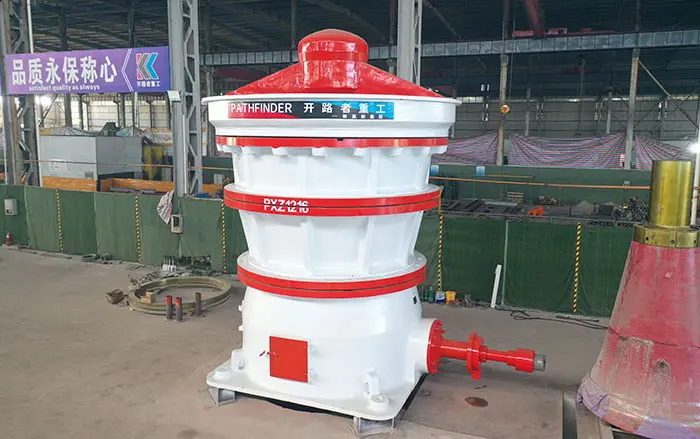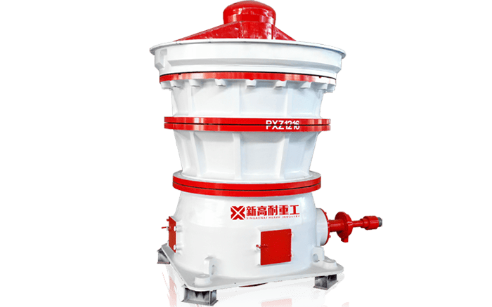
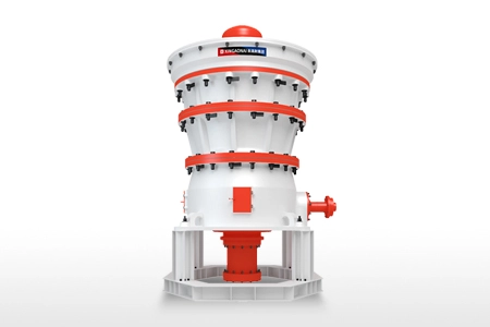
Gyratory crusher wear parts operate under continuous compression, abrasion and material impact. The mantle and concaves form the crushing chamber and experience the most direct wear, while spider caps, arm liners and internal protective liners protect the crusher structure.
Wear-part life cannot be determined by a universal number of operating hours or processed tonnes. It depends on material abrasiveness, silica content, feed distribution, closed-side setting, crushing-chamber profile and operating conditions.
Regular measurement is more reliable than waiting for capacity or product quality to decline. This guide explains the main gyratory crusher wear parts, common wear signs and the factors that determine replacement timing.
Main Gyratory Crusher Wear Parts
| Part | Function | Common wear signs |
|---|---|---|
| Mantle | Moving crushing surface | Reduced thickness, uneven profile, cracking |
| Concaves | Stationary crushing surface | Segment wear, loose sections, cracking |
| Spider cap | Protects the spider hub | Impact wear, deformation, cracking |
| Spider-arm liners | Protect the spider arms | Abrasion, loose fasteners, exposed structure |
| Bottom-shell liners | Protect lower structural surfaces | Reduced thickness, holes, loose liners |
| Feed-area liners | Protect the feed zone | Localized impact and abrasion |
| Discharge-area liners | Protect the discharge zone | Abrasion and material-flow wear |
| Dust seals | Limit dust contamination | Cracking, leakage, loss of sealing |
| Main-shaft sleeve | Protects the main-shaft surface | Scoring and dimensional wear |
| Eccentric bushing | Supports eccentric movement | Scoring, excessive clearance, overheating |
The mantle, concaves and protective liners are regular wear parts. Bushings, sleeves, bearings and seals are mechanical wear components that should be replaced according to measurements and condition rather than on the same schedule as chamber liners.
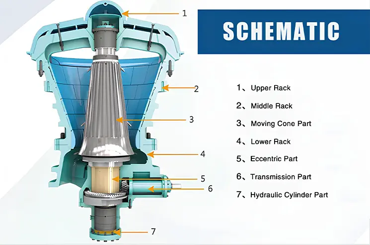
1. Mantle
The mantle is the moving wear surface installed around the crushing head. It moves in a gyrating path inside the stationary concaves and compresses material during each crushing cycle.
Common mantle wear signs
Reduced liner thickness
Uneven circumferential wear
Localized deep wear
Cracking
Surface deformation
Changes in the crushing profile
Difficulty maintaining product size
Increased power fluctuation
Uneven mantle wear is often associated with poor feed distribution, feed segregation or operation outside the recommended CSS range.
When should the mantle be replaced?
Replacement should be considered when:
Wear reaches the manufacturer’s allowable limit.
The chamber profile can no longer maintain the required product size.
Capacity declines despite stable feed conditions.
Cracks or deformation are found.
Wear creates a risk of damage to the supporting structure.
The mantle can no longer be securely retained.
Do not wait until the mantle is completely worn through.
2. Concaves
Concaves are the stationary wear surfaces fitted around the inner wall of the crushing chamber. They are normally divided into multiple segments to simplify handling and installation.
Different sections of the chamber may experience different wear rates because feed size, crushing pressure and material movement change as material travels downward.
Common concave wear signs
Uneven wear between segments
Loose concave sections
Cracks
Damaged backing material
Excessive wear in one chamber zone
Changes in product-size distribution
Exposed supporting surfaces
Concave segments should be checked for secure seating. A loose segment may cause additional damage to adjacent liners or structural components.
When should concaves be replaced?
Replacement may be required when:
Measured wear reaches the specified limit.
The chamber profile becomes inefficient.
Concave segments become loose or cracked.
The CSS cannot be maintained.
Product size becomes consistently too coarse.
The underlying shell is at risk of exposure.
Mantle and concave wear should be evaluated together because they form one crushing-chamber profile.
3. Spider Cap
The spider cap protects the upper spider hub from falling material. It receives direct impact from run-of-mine ore and oversized rock entering through the feed opening.
Inspect it for:
Impact deformation
Cracks
Reduced thickness
Loose fasteners
Material buildup
Damage exposing the spider hub
The cap should be replaced before falling material begins to damage the structural spider components.
4. Spider-Arm Liners
Spider-arm liners protect the spider arms from abrasion and direct material impact.
Uneven feed distribution can concentrate material flow on one spider arm and produce localized wear.
Inspect for:
Uneven thickness
Cracking
Loose or missing fasteners
Gaps between the liner and spider arm
Exposed structural steel
Severe localized impact marks
Replacing an arm liner is generally less complex than repairing structural damage to the spider.
5. Internal Protective Liners
Protective liners may be installed in the feed area, lower shell and discharge zone. Their purpose is to prevent abrasive material from contacting the main structural surfaces.
Replace protective liners when:
Wear approaches the specified minimum thickness.
Holes or cracks appear.
Fasteners become loose or damaged.
The supporting surface becomes exposed.
Material begins to enter behind the liner.
Internal liners should be inspected during planned shutdowns because some areas cannot be checked safely during operation.
6. Dust Seals
Dust seals help prevent fine particles from entering the eccentric, bushing and lubrication areas.
Damaged seals can lead to oil contamination and accelerated wear of expensive internal components.
Possible warning signs include:
Increased dust in the lubrication oil
Damaged or cracked seal surfaces
Oil leakage
Abnormal metal content in oil analysis
Rising oil temperature
Accelerated bushing wear
Seals should be treated as condition-based replacement components.
7. Main-Shaft Sleeve
A replaceable sleeve may be used to protect the main-shaft surface in areas exposed to sliding contact or seal wear.
Inspect for:
Scoring
Grooves
Surface deformation
Excessive clearance
Heat discoloration
Uneven contact patterns
Replacement criteria should be based on measured dimensions and manufacturer tolerances.
8. Eccentric Bushing
The eccentric bushing is not a regular crushing liner, but it is a critical mechanical wear component. It supports the eccentric movement that produces the gyrating motion of the main shaft and mantle.
Signs of possible bushing wear include:
Increasing oil temperature
Metal particles in the oil
Abnormal vibration
Excessive clearance
Scored contact surfaces
Irregular main-shaft movement
Unusual operating noise
Lubrication problems, contaminated oil, incorrect clearance and overload can accelerate bushing wear.
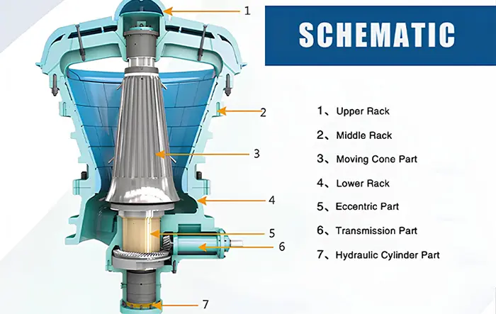
For the position and function of each component, see gyratory crusher construction and main parts.
What Causes Gyratory Crusher Wear?
Material abrasiveness
Hardness alone does not determine wear. Quartz and other silica-rich minerals can create high abrasive wear even when compressive strength is not exceptionally high.
Feed-size distribution
Feed containing excessive fines or oversized material can change chamber loading and wear distribution. Oversized material may also cause bridging and impact damage.
Uneven feeding
Continuous one-sided feeding concentrates crushing forces and material flow in one part of the chamber, causing uneven mantle and concave wear.
Closed-side setting
An excessively small CSS may increase crushing pressure, power draw and liner wear. The setting should remain within the permitted range for the selected chamber.
Crushing-chamber selection
A chamber profile that does not match the feed size and product requirement may cause poor material flow, reduced capacity and localized wear.
Moisture and clay
Wet or sticky feed can build up in the chamber, interfere with material movement and produce unstable loading.
Tramp metal
Uncrushable metal can damage the mantle, concaves and other internal components. Hydraulic overload protection reduces risk but does not replace upstream metal detection and removal.
Operating practice
Repeated starts under load, unstable feeding, blocked discharge and prolonged operation with worn liners can accelerate damage.
How to Inspect Wear Parts
Wear inspection should use consistent measurement points and documented results.
Recommended methods include:
Visual inspection
Thickness measurement
Chamber-profile templates
Photographic comparison
CSS measurement
Oil analysis
Vibration monitoring
Temperature monitoring
Power-draw analysis
Product-size analysis
Create a record for every inspection showing:
Operating hours
Processed tonnage
Measurement position
Remaining thickness
CSS
Product size
Capacity
Motor load
Observed cracks or deformation
Corrective action
Using the same measurement locations makes wear trends easier to compare.
Signs That Wear Parts Need Attention
| Operating symptom | Possible wear-related cause |
|---|---|
| Product becomes coarser | Worn mantle, concaves or changed CSS |
| Capacity decreases | Inefficient chamber profile or restricted material flow |
| Motor load fluctuates | Uneven feed or uneven liner profile |
| CSS requires frequent correction | Accelerated or uneven liner wear |
| Vibration increases | Loose liner, uneven wear or mechanical damage |
| Oil contains metal particles | Bushing, bearing, gear or sleeve wear |
| Material builds up | Poor chamber flow or damaged liners |
| Structural surface becomes visible | Protective liner has worn too far |
These symptoms are not final diagnoses. Feed conditions, discharge restrictions and mechanical faults can produce similar operating changes.
How to Extend Wear-Part Life
Maintain even feed distribution
Feed should be distributed as evenly as practical around the crushing chamber. Check the dump pocket, feed chute and upstream equipment if wear is concentrated on one side.
Use the correct chamber profile
Select the chamber according to maximum feed size, feed gradation, required capacity and target product size.
Control the CSS
Keep the closed-side setting within the approved operating range. Do not use an unnecessarily small CSS to compensate for an unsuitable chamber or downstream problem.
Remove tramp metal
Use metal detectors, magnets or other suitable protection before material enters the crusher.
Maintain the lubrication system
Clean oil at the correct pressure, temperature and flow protects bushings, bearings and drive components.
Replace liners before structural exposure
Delaying replacement may damage the crushing head, shell, spider or other high-value components.
Monitor operating trends
Changes in throughput, motor load, vibration, oil temperature and product size can reveal developing wear before visible failure occurs.
A complete inspection schedule is available in the gyratory crusher maintenance checklist.
Selecting the Correct Wear-Part Material
Wear-part material should be selected according to the actual application. The hardest available material is not automatically the best choice.
Selection factors include:
Material hardness
Abrasiveness
Silica content
Feed size
Impact loading
Crusher model
Chamber profile
CSS
Required service life
Risk of cracking
Manganese-steel grades and other alloys differ in work-hardening behaviour, toughness and wear resistance. The correct selection should balance abrasion resistance and resistance to impact cracking.
Do not replace the original liner material with an unverified alloy without confirming fit, mechanical properties and operating suitability.
Wear-Part Replacement Safety
Wear-part replacement involves suspended loads, stored energy and work inside the crusher. Before beginning:
Stop the upstream feeder.
Allow the crushing chamber to empty where possible.
Stop the crusher using the approved procedure.
Isolate electrical, hydraulic and other energy sources.
Apply lockout/tagout.
Verify zero-energy status.
Secure movable components.
Use approved lifting points and lifting tools.
Follow confined-space procedures where applicable.
Keep personnel clear of suspended components.
Never enter the crushing chamber or work beneath a suspended mantle or concave segment without the required controls.
Information Required When Ordering Wear Parts
Provide the supplier with:
Crusher manufacturer and model
Equipment serial number
Wear-part name
Original part number
Chamber profile
Current CSS
Material processed
Maximum feed size
Required product size
Abrasiveness or silica content
Photographs and measurements
Previous wear life and wear pattern
Part numbers and equipment serial numbers are more reliable than ordering only by the general crusher model name.
For the X Series Primary Gyratory Crusher, confirm the exact model and chamber configuration before ordering mantle, concaves or internal liners.
Conclusion
The mantle and concaves are the principal gyratory crusher wear parts, but spider caps, arm liners, protective liners, seals and mechanical wear components also require regular inspection.
Replacement decisions should be based on measured thickness, chamber profile, product-size changes, capacity, power draw and manufacturer limits. Fixed operating-hour or tonnage claims cannot accurately predict wear life across different materials and sites.
Consistent measurements, correct feed distribution and controlled operation make wear more predictable and help prevent damage to expensive structural components.