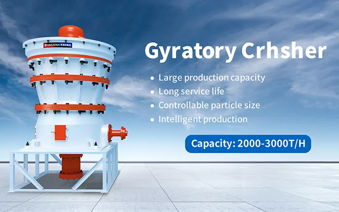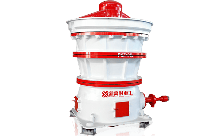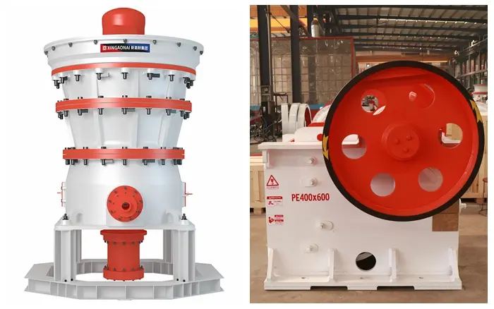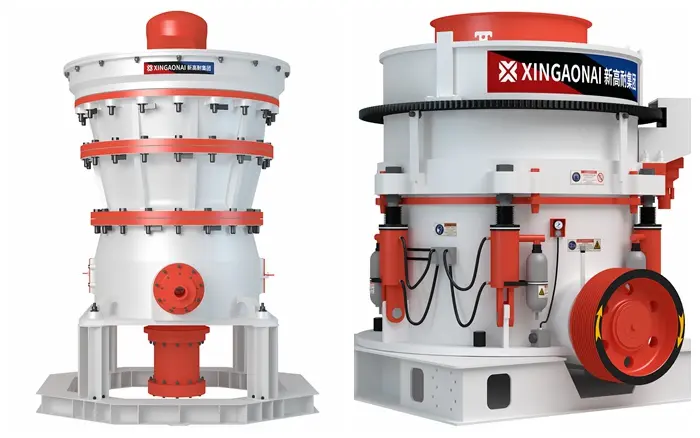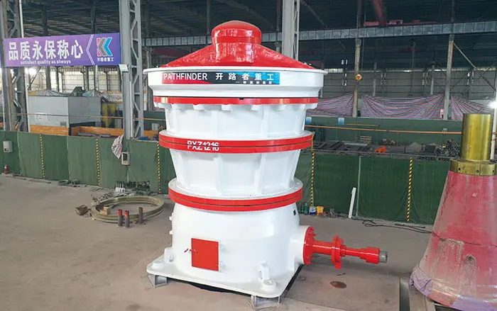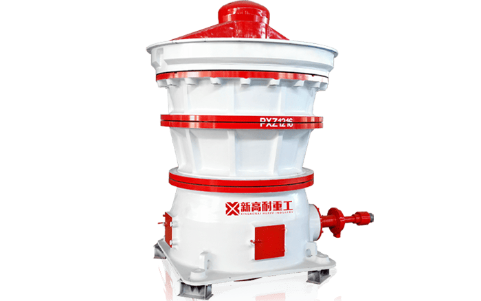
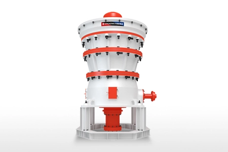
A gyratory crusher is a heavy-duty compression crusher primarily used to reduce run-of-mine ore and large blasted rock. Its structure is designed to withstand continuous crushing forces while allowing material to move downward through the crushing chamber.
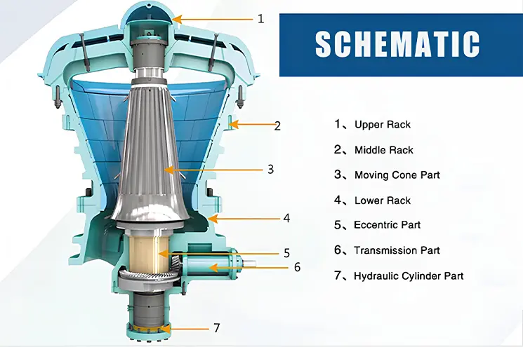
The main components include the spider assembly, main shaft, mantle, concaves, eccentric assembly, main frame, drive system, hydraulic system and lubrication system. Each component performs a specific mechanical or protective function.
Understanding the construction of a gyratory crusher helps operators identify wear, plan maintenance and select the correct equipment for a mining or quarrying project.
Main Parts of a Gyratory Crusher
| Component | Primary function |
|---|---|
| Spider assembly | Supports and guides the upper end of the main shaft |
| Main shaft | Supports the mantle and transfers gyrating motion |
| Mantle | Moving crushing surface |
| Concaves | Stationary crushing surface |
| Main frame | Supports the crushing chamber and major components |
| Eccentric assembly | Produces the gyrating movement |
| Drive system | Transfers motor power to the eccentric assembly |
| Hydraulic system | Adjusts main-shaft position and CSS |
| Lubrication system | Protects bearings, gears and bushings |
| Dust seal | Limits contamination of internal components |
| Protective liners | Protect structural surfaces from wear and impact |
Component design and arrangement vary by manufacturer and crusher model. Always use the technical drawings and maintenance manual supplied for the actual equipment.
1. Spider Assembly
The spider assembly is installed across the top of the crusher. It supports and guides the upper end of the main shaft through the spider bearing.
Its main components may include:
Spider hub
Spider arms
Spider bearing
Spider bushing
Spider cap
Spider-arm liners
The spider arms are exposed to falling feed material and therefore require protective liners. The spider cap and liners reduce direct impact and abrasive wear on the structural parts.
Common inspection points include:
Spider-arm liner wear
Loose fasteners
Cracks
Lubrication condition
Bearing clearance
Material buildup
Abnormal movement
The spider bearing guides the main shaft but does not contain the lower eccentric assembly. The eccentric assembly is located in the lower section of the crusher.
2. Main Shaft
The main shaft is a major load-bearing component that supports the crushing head and mantle. Its lower section interacts with the eccentric assembly, while its upper end is guided by the spider bearing.
When the eccentric rotates, the main shaft does not simply rotate around its own centre. Instead, it follows a controlled gyrating path that moves the mantle toward and away from the concaves.
The main shaft must withstand:
Crushing forces
Bending loads
Repeated cyclic loading
Weight of the crushing head
Loads caused by uneven feeding
Important inspection areas include surface wear, cracks, scoring, lubrication condition and dimensional tolerances.
3. Mantle
The mantle is the moving crushing surface fitted around the crushing head or main-shaft assembly. It moves continuously inside the stationary concaves.
As the mantle approaches the concaves, rock and ore are compressed and fractured. As it moves away, the crushing gap opens and the material falls lower in the chamber.
Mantles are normally manufactured from wear-resistant manganese steel or another alloy selected for the material and operating conditions.
Mantle wear is affected by:
Material hardness
Abrasiveness
Silica content
Feed-size distribution
Feed segregation
Closed-side setting
Throughput
Chamber profile
A worn mantle changes the crushing-chamber profile and may affect capacity, product size and power draw.
4. Concaves
Concaves are the stationary wear surfaces installed around the inner wall of the upper shell and main frame. Together with the mantle, they form the crushing chamber.
Concaves are normally divided into multiple segments to simplify installation and replacement. Different sections of the crushing chamber may use different liner shapes or materials according to the wear pattern.
Concave design affects:
Feed acceptance
Crushing-chamber volume
Nip conditions
Product-size distribution
Capacity
Liner wear
Loose, cracked or excessively worn concave segments should be addressed before they expose the supporting structure or affect crusher operation.
For more information about liner inspection and replacement, see the gyratory crusher wear parts guide.
5. Crushing Chamber
The crushing chamber is the space formed between the moving mantle and stationary concaves. Its profile determines how material is received, compressed and discharged.
A correctly selected chamber should match:
Maximum feed size
Feed-size distribution
Required capacity
Required product size
Material hardness
Material abrasiveness
Closed-side setting
Eccentric throw
An unsuitable chamber profile can cause:
Reduced capacity
Bridging
Poor product-size control
Uneven liner wear
High power draw
Unstable crusher loading
The chamber should be selected using actual feed and production data rather than the feed opening alone.
6. Main Frame and Shell Sections
The main frame supports the crushing chamber, main shaft, eccentric assembly and drive components. Large gyratory crushers may use several frame or shell sections connected by heavy-duty fastening systems.
The structure must resist:
Static equipment weight
Dynamic crushing forces
Material impact
Drive-system loads
Vibration
Foundation movement
Protective liners are used in areas exposed to falling or discharged material. If these liners become excessively worn, the underlying structural surfaces may be damaged.
Inspection should include:
Cracks
Loose fasteners
Abnormal movement
Worn mounting surfaces
Damaged protective liners
Foundation connections
Structural repairs should follow an approved engineering and welding procedure.
7. Eccentric Assembly
The eccentric assembly is located in the lower part of the crusher. Its function is to convert the rotational input from the drive system into the gyrating movement of the main shaft and mantle.
Depending on the design, the assembly may include:
Eccentric sleeve
Eccentric bushing
Gear
Pinion
Supporting bearings
Thrust components
The eccentric bushing operates under high load and depends on a clean, stable lubrication supply.
Possible signs of eccentric or bushing problems include:
Rising oil temperature
Metal particles in the oil
Abnormal vibration
Increased clearance
Irregular main-shaft movement
Unusual noise
The eccentric bushing should not be described as being inside the spider hub. The spider assembly is at the top of the crusher, while the eccentric assembly is in the lower section.
8. Drive System
The drive system transfers power from the electric motor to the eccentric assembly.
A typical system may include:
Electric motor
Coupling
Drive shaft
Pinion
Gear
Bearings
Protective guards
As the motor drives the pinion and gear, the eccentric assembly moves the main shaft and mantle in a gyrating path.
Drive-system inspection should include:
Alignment
Coupling condition
Gear contact
Bearing temperature
Lubrication
Fasteners
Abnormal noise
Guard condition
The motor power and drive arrangement depend on crusher size, chamber design and expected crushing load.
9. Hydraulic Adjustment System
The hydraulic system supports or adjusts the main-shaft position, depending on the crusher design. Raising or lowering the main shaft changes the closed-side setting.
The system is used to:
Adjust discharge size
Compensate for mantle and concave wear
Maintain the required CSS
Support the main shaft
Provide overload protection in suitable designs
The hydraulic system may increase the discharge opening when an uncrushable object enters the chamber. However, hydraulic protection does not replace upstream metal detection and removal equipment.
Typical hydraulic components include:
Hydraulic cylinder or support piston
Oil tank
Pump
Valves
Accumulator
Pressure sensors
Pipes and hoses
10. Lubrication and Cooling System
The lubrication system supplies clean oil to critical moving components, including bearings, bushings, gears and the eccentric assembly.
A typical system may contain:
Main oil pump
Standby oil pump
Oil tank
Filters
Oil cooler
Temperature sensors
Pressure sensors
Flow sensors
Alarms and interlocks
The system should be operating before the main crusher motor starts. Correct oil pressure, flow and temperature must be confirmed before crushing begins.
Poor lubrication may lead to:
Bearing damage
Bushing wear
Gear damage
High temperature
Abnormal vibration
Unplanned shutdown
Detailed inspection requirements are available in the gyratory crusher maintenance checklist.
11. Dust-Sealing System
The dust-sealing system helps prevent fine particles from entering the eccentric, bearing and lubrication areas.
The system may use:
Dust seals
Seal rings
Covers
Pressurized air
Oil-based sealing arrangements
Seal condition is particularly important when the crusher processes dry, dusty or abrasive material. Damaged seals can contaminate the lubricating oil and accelerate internal wear.
Oil analysis may help identify dust, water and abnormal metal contamination before serious damage occurs.
12. Protective Liners
Protective liners are installed on structural surfaces exposed to falling material, abrasive flow or repeated impact.
These may include:
Spider-arm liners
Bottom-shell liners
Feed-area liners
Discharge-area liners
Internal frame liners
Protective liners should be replaced before the underlying frame or shell becomes exposed. Replacing a liner is generally less complex than repairing structural damage.
How the Components Work Together
Run-of-mine ore or blasted rock enters through the upper feed opening and falls into the chamber between the mantle and concaves.
The drive system rotates the eccentric assembly, causing the main shaft and mantle to move in a gyrating path. Material is compressed when the mantle moves toward the concaves and moves downward when the gap opens.
This process repeats until the material is small enough to pass through the bottom discharge opening.
The hydraulic system controls the main-shaft position and closed-side setting, while the lubrication system protects the bearings, bushings and drive components.
For a complete process explanation, see how a gyratory crusher works.
Which Parts Are Wear Parts?
Not every crusher component is a regularly replaced wear part.
Regular wear parts
Mantle
Concave segments
Spider cap
Spider-arm liners
Bottom-shell liners
Other protective liners
Components subject to mechanical wear
Eccentric bushing
Spider bushing
Main-shaft sleeve
Bearings
Dust seals
Gear and pinion
Mechanical components should be inspected and measured. They should not automatically be replaced at the same interval as the mantle and concaves.
How Construction Affects Crusher Selection
The construction of a gyratory crusher determines its feed capacity, crushing performance, installation requirements and maintainability.
Before selecting a model, consider:
Maximum feed size
Feed-size distribution
Material hardness
Abrasiveness
Required capacity
Required product size
Chamber profile
CSS range
Motor power
Foundation requirements
Maintenance access
Available lifting equipment
A larger feed opening alone does not guarantee that the crusher is suitable for the project. The chamber, eccentric throw, drive power and discharge system must also match the application.
The X Series Primary Gyratory Crusher is available in multiple sizes for different feed openings and capacity requirements. Final selection should be based on actual feed and operating data.
Conclusion
A gyratory crusher is built around a heavy-duty main frame, a gyrating main shaft and mantle, stationary concaves and a lower eccentric assembly. The spider guides the upper end of the main shaft, while hydraulic and lubrication systems control the setting and protect critical components.
Understanding the function of each part makes it easier to identify abnormal wear, plan shutdown work and select the correct crusher for a project. Equipment selection should consider the complete chamber, drive, hydraulic, lubrication and installation system—not only the feed opening or nominal capacity.