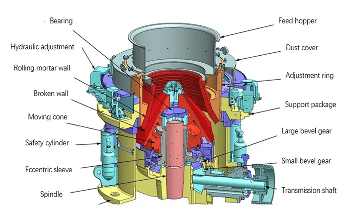
Cone crusher bearings support moving assemblies and transmit operating loads through the machine. However, the term “bearing” does not describe one universal component.
Depending on the crusher design and assembly position, the support system may include rolling bearings, plain bearings, eccentric bushings, head bushings, socket liners or thrust-bearing components.
These parts have different working surfaces, lubrication requirements, clearances and replacement procedures. A bearing selected only by its approximate size—or a bushing selected only by its material colour—may be unsuitable for the installed crusher.
This guide explains how to identify the support arrangement, recognize possible damage and prepare the information needed for a replacement review.
First Identify the Crusher and Assembly Position
Before comparing bearing types, establish which component is being discussed.
Record:
Crusher manufacturer;
Model and serial number;
Assembly position;
Original part number;
Drawing reference;
Previous modifications;
Visible markings;
Photographs before removal.
A pinion-shaft bearing and an eccentric bushing perform different duties even when both are described as “cone crusher bearings.”
The same crusher may contain several support arrangements. Identifying one rolling bearing does not establish that the head or eccentric assembly uses the same technology.
For the surrounding components, refer to the cone crusher parts guide.
Rolling Bearings, Bushings and Thrust Supports
| Component category | How it supports movement | Information needed for identification |
|---|---|---|
| Rolling bearing | Uses rolling elements between raceways | Complete designation, suffixes, dimensions and assembly position |
| Plain bearing or bushing | Uses relative sliding across a lubricated bearing surface | Part number, material, geometry, oil passages, fits and clearances |
| Socket or spherical sliding support | Supports a mating curved surface in applicable designs | Surface geometry, mating component and lubrication arrangement |
| Thrust support | Carries load along the relevant axis | Load direction, stack arrangement, thickness and specified clearances |
These categories describe functions. The actual combination must be checked against the crusher documentation.
Rolling Bearings
Some crusher assemblies use cylindrical, tapered, spherical or other rolling-bearing arrangements.
Each type has a particular load capability and installation requirement. Internal clearance, cage construction, dimensional tolerances and other designation details can affect compatibility.
A spherical rolling bearing should not be confused with a spherical sliding support merely because both names contain “spherical.”
Bushings and Plain Bearings
Bushings provide a sliding bearing surface between mating components.
Depending on the machine, these may include eccentric bushings, head bushings or other model-specific support parts. Some use bronze alloys or other specified bearing materials.
Their performance depends on more than the bore diameter. Oil grooves, ports, surface condition, installed geometry, operating clearance and lubricant supply all matter.
Thrust Components
Thrust bearings, washers or plates support axial loads in the arrangement specified by the crusher design.
Their orientation and assembled thickness can affect positioning and clearance. Treating a thrust component as a simple spacer can lead to an incorrect assembly.
Locate the Part Before Interpreting Its Wear
A component’s location helps explain the loads and movement it experiences.
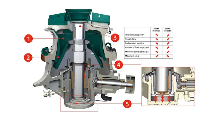
Depending on the crusher, support positions may include:
Drive or pinion-shaft assembly;
Eccentric assembly;
Main-shaft interface;
Head-support assembly;
Axial or thrust-support arrangement.
The load path and relative movement vary between designs. Main-shaft, eccentric and head arrangements should not be assumed identical across spring, single-cylinder and multi-cylinder machines.
Use the cone crusher structural diagram guide as an introduction, then confirm the installed arrangement from the model-specific drawing.
What Can Indicate Bearing or Bushing Damage?
Possible warning signs include:
An unexplained temperature increase;
New mechanical noise;
Changed vibration;
Metallic debris in the lubricant or filter;
Scoring on a sliding surface;
Excessive measured clearance;
Lubricant leakage;
Abnormal movement;
Repeated lubrication alarms.
None of these symptoms identifies the failed component by itself.
For example, high oil temperature may result from a cooling problem, unsuitable lubricant, restricted flow, abnormal load or internal damage. Replacing a bearing without investigating the complete condition may leave the cause unresolved.
Record when the symptom began and whether it followed a lubricant change, component replacement, setting adjustment or unusual operating event.
Distinguish Rolling-Bearing Damage from Bushing Damage
Rolling-Bearing Warning Signs
Inspection findings may include:
Raceway flaking or spalling;
Indentations;
Roller damage;
Cage damage;
Corrosion;
Smearing;
Abnormal contact patterns;
Evidence of ring movement on its seat.
These findings require assessment alongside mounting fits, lubrication, contamination and loading.
A visible mark should not automatically be interpreted as normal wear or as proof of one particular cause.
Bushing and Sliding-Surface Warning Signs
Possible findings include:
Directional scoring;
Localized wiping or smearing;
Embedded particles;
Uneven contact;
Cracking;
Material transfer;
Damaged oil grooves;
Clearance outside the specified limit;
Damage to the mating shaft or eccentric surface.
A new bushing cannot compensate for an out-of-round housing, damaged mating surface or blocked oil passage.
Measure the connected components before deciding the repair scope.
Thrust-Surface Warning Signs
Inspect for:
Uneven contact;
Scoring;
Cracks;
Abnormal wear steps;
Local overheating;
Distortion;
Incorrect assembled clearance.
Record the original stack order and orientation during disassembly so the findings can be compared with the required arrangement.
Investigate Lubrication Before Replacing Parts
Correct lubrication supports the bearing surfaces and helps control heat and contamination.
For an oil-lubricated assembly, useful records may include:
Lubricant identification;
Oil level;
Supply and return temperatures;
Pressure at the specified measuring location;
Oil flow where measured;
Filter condition;
Cooler condition;
Pump operation;
Alarm history;
Oil-analysis results.
Compare readings with the manufacturer’s limits and the machine’s established operating baseline.
Oil Level Does Not Prove Oil Delivery
A reservoir can contain oil while an internal passage receives insufficient flow.
Pump condition, restrictions, leaks, relief devices and internal clearances can affect delivery. Pressure alone should not be treated as a complete diagnosis.
Lubrication and Hydraulic Functions Must Be Identified Separately
A crusher may have a combined service unit, but lubrication and hydraulic adjustment perform different functions.
Lubrication protects designated moving interfaces. Hydraulic functions may include adjustment, clamping, support or overload release, depending on the machine.
Do not assume the circuits use interchangeable oils or share the same operating limits.
For the adjustment and protection functions, see the cone crusher hydraulic system guide.
Do Not Add Grease to an Unidentified Lubrication Point
A grease-lubricated drive bearing and an oil-fed internal bushing may require different products and procedures.
Confirm the exact lubrication point and specification before servicing. A lubricant described as “heavy-duty” or “high-temperature” is not automatically suitable.
Use Contamination Evidence Carefully
Metallic debris can help locate a developing problem, but appearance alone rarely establishes its source.
Possible sources include:
Bearings;
Bushings;
Gears;
Thrust components;
Residual debris from previous damage;
Contamination introduced during maintenance.
Preserve relevant filter material, samples and photographs for inspection.
Where practical, take oil samples before draining or cleaning the system. Document the sampling point and operating condition so results can be interpreted consistently.
If an internal component has failed, assess the connected oil circuit. Installing a replacement into a contaminated system can cause further damage.
When Does the Crusher Need to Stop?
Follow the machine’s alarm and shutdown requirements.
A prompt shutdown and inspection may be necessary when there is:
A lubrication-supply failure;
Rapidly rising temperature;
Grinding or severe mechanical noise;
Evidence of seizure;
Significant metallic debris;
Abnormal movement;
A damaged support assembly.
Do not bypass protection or repeatedly restart a machine after an unresolved lubrication trip.
Before opening the crusher, isolate electrical and stored hydraulic or mechanical energy under the site procedure. Secure supported assemblies using the specified lifting and blocking arrangements.
Routine inspection planning is covered in the cone crusher maintenance guide. Lubricant grades, limits and service intervals must come from the installed machine’s documentation.
Confirm the Full Replacement Specification
For Rolling Bearings
Provide:
Complete bearing designation;
All suffixes and markings;
Manufacturer;
Bore, outside diameter and width;
Assembly position;
Clearance or preload requirement;
Required tolerance and cage specification;
Associated seals and retaining parts;
Shaft and housing condition.
Matching the principal dimensions is necessary but may not be sufficient.
Do not mix rings or rolling assemblies from different sets unless the bearing design and manufacturer explicitly permit that arrangement.
For Bushings
Provide:
Crusher model and serial number;
Original part number;
Material specification;
Inside and outside dimensions;
Length and flange dimensions;
Oil-groove and port arrangement;
Locating features;
Installation fit;
Required running clearance;
Drawing and revision reference.
Measurements taken from a worn component should be identified as worn dimensions. They should not be used automatically as manufacturing dimensions.
For Thrust Components
Confirm:
Part number;
Position and orientation;
Material;
Thickness;
Mating geometry;
Lubrication features;
Stack arrangement;
Required assembly clearance.
Inspect Mating Parts Before Assembly
Replacement work should include the surfaces and components connected to the damaged part.
Check, as applicable:
Shaft or journal;
Housing bore;
Eccentric surface;
Thrust mating face;
Seats and locating shoulders;
Oil passages;
Seals;
Retainers;
Fasteners;
Gear and drive condition.
Installation fit, heating method, assembly force and clearance checks are specific to the part and crusher.
Do not improvise machining allowances, heating temperatures or tightening values from another machine.
After assembly, verify lubrication delivery, required clearances and protective functions before the controlled restart.
Why Does a New Bearing or Bushing Fail Again?
Repeated damage suggests that part replacement did not address the complete cause.
Investigate:
Contamination remaining in the system;
Incorrect lubricant;
Restricted oil supply;
Damaged mating surfaces;
Incorrect fits or clearances;
Assembly error;
Unsuitable replacement specification;
Abnormal loading;
Seal failure;
Unresolved drive or structural problems.
Record the time between replacement and renewed symptoms. A problem appearing immediately after assembly may point toward a different cause from one developing gradually during service.
Identifying Parts for XINGAONAI Cone Crushers
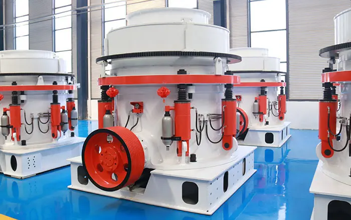
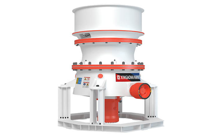
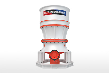
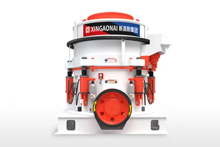
Use the exact equipment identity when requesting component information for the XCS Series Single Cylinder Hydraulic Cone Crusher or XHP Series Multi-Cylinder Hydraulic Cone Crusher.
Provide the machine serial number, assembly position, original part number and available drawings.
A product-series name alone does not establish the bearing arrangement or prove interchangeability between machines. Configuration and component revisions must also be checked.
For equipment from another manufacturer, submit the available identification and dimensions for a compatibility review rather than assuming a direct replacement is available.
Confirm the Arrangement Before Replacing the Part
Reliable cone crusher bearing and bushing replacement begins with identifying the actual support arrangement.
Use the component location, part number and drawing to establish what is installed. Review damage alongside lubrication condition, mating surfaces, clearances and operating history.
Send XINGAONAI the machine identity, component details and inspection records to request a model-specific parts review.