Crusher reduction ratio describes how much the size of a material is reduced as it passes through a crusher. It is an important engineering parameter for evaluating the size-reduction duty of an individual crusher and determining how that duty should be distributed across a multi-stage crushing circuit.
A higher reduction ratio does not automatically mean better crushing performance. In many hard-rock applications, reducing very large feed directly to a fine final product in a single stage is neither practical nor desirable.
Instead, the total size reduction is divided among primary, secondary and sometimes tertiary crushing stages.
Understanding crusher reduction ratio helps answer three practical questions:
How much size reduction is required?
Can one crushing stage reasonably achieve it?
How should the total reduction be distributed across the crushing circuit?
What Is Crusher Reduction Ratio?
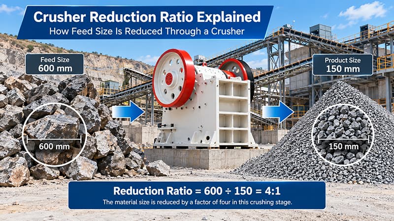
In its simplest form, the reduction ratio compares the size of the material entering a crusher with the size of the material leaving it:
Reduction Ratio = Feed Size ÷ Product Size
For example, if a crushing stage reduces material from 600 mm to 150 mm:
600 ÷ 150 = 4
The reduction ratio is therefore:
4:1
However, particle size in a real crushing circuit is not represented by a single dimension. Both the feed and crusher product contain a range of particle sizes.
For this reason, the basis used for calculating the ratio should always be stated clearly.
Maximum Feed Size vs Maximum Product Size
A simple calculation may compare the maximum feed particle with the maximum product particle:
R = Maximum Feed Size ÷ Maximum Product Size
This method is useful for quickly describing the size change through a crusher, but it does not represent the complete particle-size distribution.
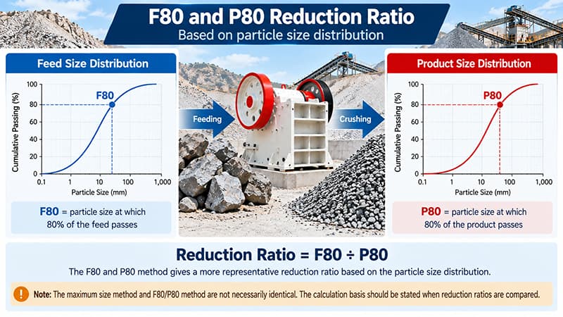
F80/P80 Reduction Ratio
A more representative approach in mineral processing is:
R80 = F80 ÷ P80
Where:
F80 is the particle size at which 80% of the feed passes.
P80 is the particle size at which 80% of the crusher product passes.
For example:
F80 = 400 mm
P80 = 100 mm
Therefore:
R80 = 400 ÷ 100 = 4:1
The maximum-size method and F80/P80 method should not be mixed when comparing crushers or crushing stages.
How to Calculate Crusher Reduction Ratio
The calculation is simple once the feed and product size basis has been defined.
Consider a crusher with:
Feed F80 = 600 mm
Product P80 = 150 mm
Then:
Reduction Ratio = 600 ÷ 150 = 4:1
This means the characteristic particle size has been reduced by a factor of four through that crushing stage.
The calculation becomes more useful when applied to an entire crushing circuit.
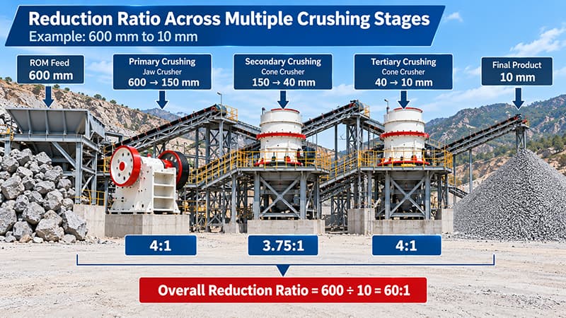
Suppose a plant needs to reduce material through three stages:
600 mm → 150 mm → 40 mm → 10 mm
The stage reduction ratios are:
Primary Crushing
600 ÷ 150 = 4:1
Secondary Crushing
150 ÷ 40 = 3.75:1
Tertiary Crushing
40 ÷ 10 = 4:1
The overall plant reduction ratio is:
600 ÷ 10 = 60:1
A 60:1 overall reduction does not mean that one crusher must provide a reduction ratio of 60:1.
Instead:
4 × 3.75 × 4 = 60
The total size reduction is distributed across the three crushing stages.
Reduction Ratio Across Multiple Crushing Stages
Multi-stage crushing is particularly important when processing hard rock or when there is a large difference between the run-of-mine feed size and the required final product.
A typical circuit may be represented as:
ROM Feed → Primary Crushing → Secondary Crushing → Tertiary Crushing → Final Product
The primary stage normally handles the largest feed and produces material suitable for the next crusher.
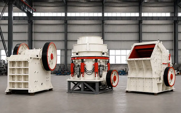
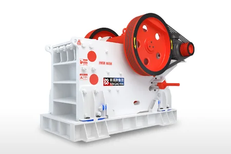
A PEV Series Jaw Crusher can be used for primary crushing in mining and aggregate applications where large feed material must be reduced.
The secondary stage performs additional reduction.
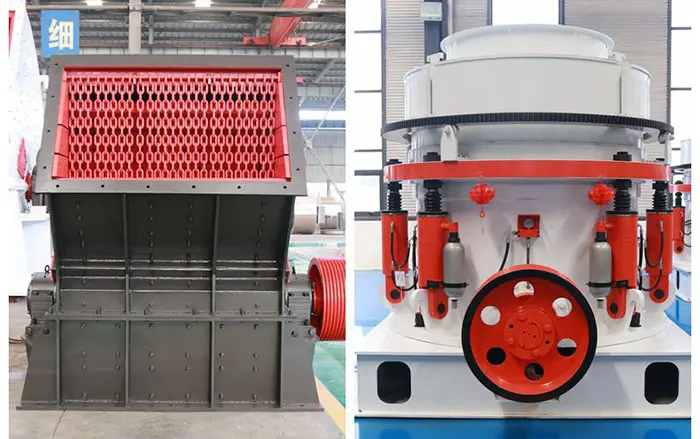
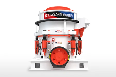
For hard and abrasive materials, an XHP Multi-Cylinder Hydraulic Cone Crusher can reduce the primary crusher product to a smaller and more controlled size.
A tertiary stage may be added when the required final product is smaller or tighter size control is needed.
The key principle is:
The overall plant reduction ratio is not the required reduction ratio of a single crusher.
Distributing the reduction duty provides better control over intermediate and final product sizes and allows each crusher to operate in an appropriate position within the circuit.
How Reduction Characteristics Differ by Crusher Type
Different crusher types do not perform exactly the same size-reduction duty because their crushing mechanisms, feed requirements and typical positions in the circuit differ.
| Crusher type | Typical crushing stage | Reduction characteristic |
|---|---|---|
| Jaw crusher | Primary | Moderate reduction of large feed |
| Gyratory crusher | Primary | Continuous primary reduction at high throughput |
| Cone crusher | Secondary or tertiary | Controlled reduction of pre-crushed material |
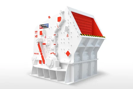
| Impact crusher | Primary or secondary | Relatively high reduction for suitable materials |
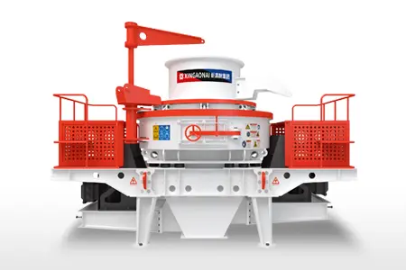
| VSI crusher | Tertiary or quaternary | Fine reduction and particle shaping |
These descriptions should not be treated as fixed reduction ratios.
The achievable ratio varies according to:
Crusher design
Crushing-chamber geometry
Feed gradation
Operating setting
Material hardness
Abrasiveness
Moisture and clay content
Desired product-size distribution
Choosing a crusher solely because it is advertised as having a high reduction ratio can therefore be misleading.
If the objective is to compare crushing mechanisms and applications, see the Stone Crusher Types Guide.
What Determines the Achievable Reduction Ratio?
The theoretical ratio required by a process and the ratio that a crusher can achieve reliably are not always the same.
Several factors influence the practical reduction duty.
Feed Size
The difference between the incoming feed size and the required discharge size determines the amount of reduction needed.
Large run-of-mine feed combined with a fine target product often requires more than one crushing stage.
Crusher Type
Different crushing mechanisms are suited to different duties.
A jaw crusher commonly handles large primary feed, while a cone crusher is generally used after primary crushing for further reduction.
An impact crusher can provide a different reduction characteristic for suitable softer or less abrasive materials.
Reduction ratio alone should not be used to select among these machines. Material hardness, abrasiveness, capacity, feed size and product requirements must also be considered.
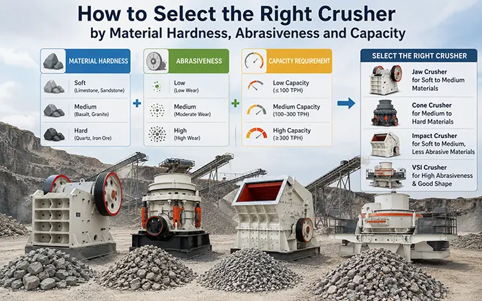
For this decision, see How to Select the Right Crusher by Material Hardness, Abrasiveness and Capacity.
Material Characteristics
Hardness, abrasiveness, fracture behavior, moisture and clay content influence how effectively material breaks inside a crusher.
Two materials with the same feed and target product size may therefore require different crushing arrangements.
Crusher Setting
The operating setting affects the product size and therefore influences the achieved reduction ratio.
However, reduction ratio and crusher setting are not the same parameter. Setting adjustment should be evaluated separately when controlling product size.
Crushing Circuit Configuration
Screening and recirculation influence how the plant reaches its required final product size.
In a closed circuit, oversized particles can be returned for additional crushing instead of forcing all the required reduction to occur in a single pass.
Can a Crusher Reduction Ratio Be Too High?
Yes.
It is tempting to assume that a crusher capable of a larger reduction ratio is always more efficient. In practice, the objective is not to maximize the reduction ratio of every machine.
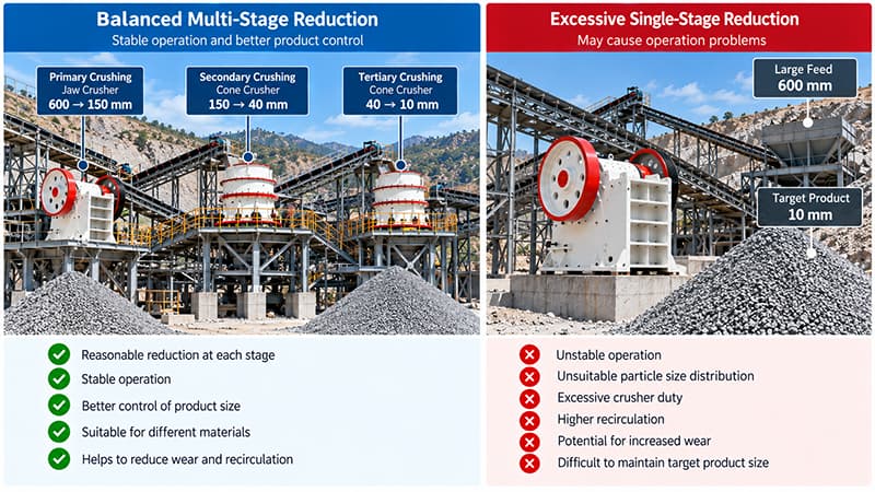
Trying to force excessive size reduction into one stage may contribute to:
Unstable operation
Unsuitable product-size distribution
Excessive crushing duty
Increased recirculating material
Accelerated wear under certain operating conditions
Difficulty maintaining the required final product consistently
For hard-rock circuits in particular, staged reduction is often more practical than asking one crusher to reduce very large feed directly to a fine product.
The better question is not:
How high can the reduction ratio be?
It is:
How should the required reduction be distributed across the circuit?
Using Reduction Ratio in Crushing Circuit Design
Consider a project with:
Feed size = 800 mm
Required final crushing product = 20 mm
The theoretical overall reduction ratio is:
800 ÷ 20 = 40:1
This does not automatically determine which crusher should be purchased.
Instead, the circuit designer can work backward through the required size reduction:
800 mm ROM Feed
↓
Primary Crushing
↓
Intermediate Product A
↓
Secondary Crushing
↓
Intermediate Product B
↓
Tertiary Crushing if Required
↓
20 mm Final Product
The engineering questions become:
What intermediate size should primary crushing achieve?
What reduction duty should the secondary stage handle?
Is tertiary crushing required?
Which crusher type is appropriate for each stage?
Is closed-circuit screening required?
How much operating margin is needed?
Reduction ratio therefore acts as a circuit-design parameter, not a stand-alone machine performance target.
Reduction Ratio Is a Circuit Parameter, Not a Performance Target
A high crusher reduction ratio does not automatically indicate better crushing performance.
The more important objective is to achieve the required size reduction in a stable and practical way across the complete circuit.
For a multi-stage plant, evaluate:
Feed Size → Primary Reduction → Secondary Reduction → Tertiary Reduction → Required Product Size
XINGAONAI evaluates material characteristics, feed size, target product size, capacity and stage-by-stage reduction requirements when configuring crushing equipment.
Providing the material type, maximum feed size or F80, required product size or P80 and target capacity gives engineers a stronger basis for developing a preliminary crushing circuit.
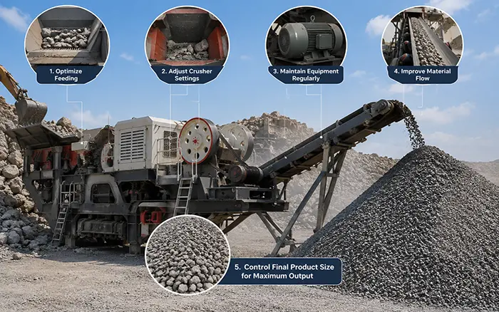
After commissioning, the actual reduction ratio should be evaluated together with throughput, power consumption, wear, recirculating load and product gradation. If the required product is achieved but plant capacity remains below target, see How to Increase Stone Crusher Capacity and Production.