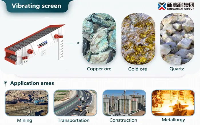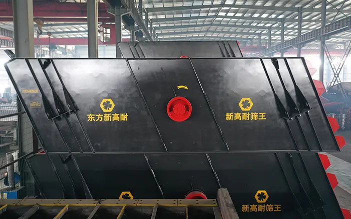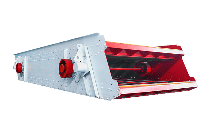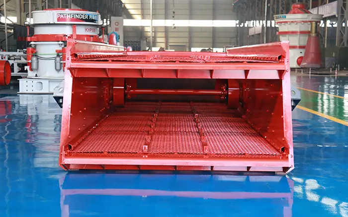
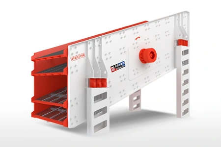
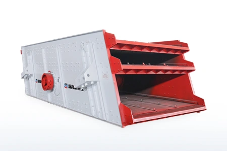
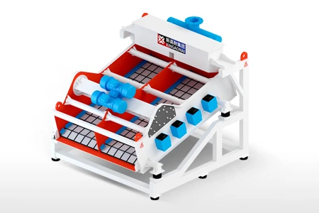
A vibrating screen contains more than screen mesh. Its screening performance depends on the interaction between the screen media, exciter, bearings, drive system, springs, screen box and feeding components.
When screening performance drops, replacing the most visible part may not solve the underlying problem. Premature screen-media failure, for example, may result from loose tensioning hardware, damaged support bars, uneven feeding or abnormal screen-box movement.
This guide explains the main vibrating screen parts, their functions, common warning signs and the information required when ordering replacements. Because part arrangements differ between circular, linear and electromagnetic screens, every replacement should be checked against the machine model, drawings and operating conditions.
Safety note: Do not inspect, adjust or replace vibrating screen components while the machine is operating. Isolate and lock out the equipment according to the site’s safety procedure before beginning an inspection.
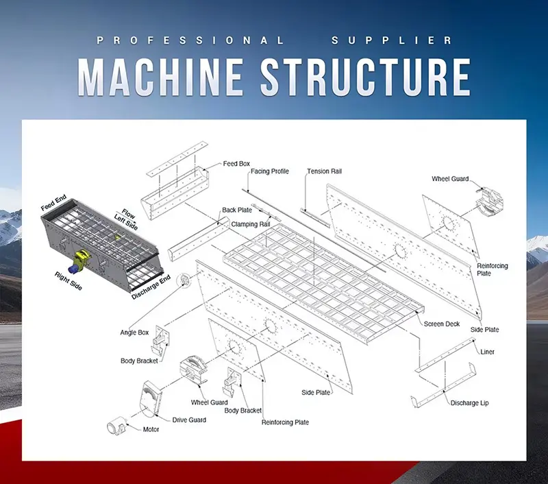
Main Vibrating Screen Parts at a Glance
A typical mining or aggregate vibrating screen contains the following component groups.
| System | Main parts | Primary function | Common warning signs |
|---|---|---|---|
| Screening system | Screen media, panels, tension rails, clamps and support bars | Separate material according to particle size | Holes, loose panels, inaccurate product size |
| Excitation system | Exciter, eccentric shaft, counterweights and gears | Generate the required vibration | Abnormal noise, heat, oil leakage or amplitude changes |
| Bearing system | Bearings, housings, seals and lubrication components | Support rotating exciter components | Excessive temperature, noise, vibration or lubricant leakage |
| Drive system | Motor, belts, pulleys, couplings and cardan shaft | Transfer power to the exciter | Belt slip, misalignment, noise or inconsistent speed |
| Support system | Coil springs, rubber springs, mounts and spring seats | Support and isolate the vibrating screen | Uneven screen height, excessive movement or cracked springs |
| Structural system | Screen box, side plates, cross members and deck frame | Carry the material and dynamic load | Cracks, loose fasteners or deformation |
| Auxiliary system | Feed box, liners, spray pipes and discharge lips | Distribute material and protect high-wear areas | Uneven feed, leakage or concentrated wear |
The exact parts arrangement depends on the screen design. A part used on one machine should not be assumed to fit another machine simply because both are described as vibrating screens.
1. Screening-Surface Parts
The screening surface consists of more than the replaceable mesh or panel. It may include:
Woven wire screen mesh;
Polyurethane panels;
Rubber screen panels;
Perforated plate;
Tension rails;
Pressure plates;
Clamps and bolts;
Modular panel fasteners;
Deck support bars;
Protective rubber profiles.
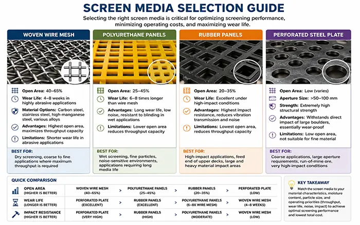
The screen media creates the openings through which correctly sized particles pass. The support and fastening parts keep the media in position and prevent uncontrolled movement against the deck structure.
Loose or incorrectly supported media may produce metallic noise, irregular openings and concentrated wear. Replacing only the mesh may not correct the problem if the tension rails, support bars or fastening hardware are damaged.
Screen-media selection requires consideration of aperture, open area, moisture, abrasiveness, impact load and fastening method. These factors are covered separately in the vibrating screen deck and media selection guide.
When ordering screening-surface parts, provide:
Deck position;
Overall media dimensions;
Aperture size and shape;
Panel thickness or wire diameter;
Screen-media material;
Hook or edge preparation;
Fastening method;
Support-rail spacing;
Photographs of the installed media.
2. Exciter, Eccentric Shaft and Counterweight Parts
The excitation system creates the vibration that moves and stratifies material on the screen surface.
Depending on the machine design, the system may contain:
Eccentric shaft;
Exciter housing;
Eccentric weights;
Counterweights;
Gear set;
Main shaft;
Bearing assembly;
End covers;
Oil seals;
Labyrinth seals;
Lubrication lines;
Mounting bolts.
A circular-motion screen may use an eccentric shaft or exciter to generate its motion. A linear screen generally uses synchronized excitation to produce directional movement. Electromagnetic screens use a different excitation principle and should not be treated as mechanically identical to conventional mining screens.
Possible warning signs around an exciter include:
New or increasing mechanical noise;
Oil or grease leakage;
Excessive housing temperature;
A change in vibration amplitude;
Uneven movement between the two sides;
Loose mounting bolts;
Visible movement between the exciter and mounting surface.
These symptoms do not automatically prove that the complete exciter must be replaced. Lubrication, alignment, drive condition, fasteners and structural support should also be checked.
Before ordering an exciter or shaft assembly, confirm:
Machine manufacturer and model;
Exciter model or assembly number;
Rotation direction;
Mounting-hole arrangement;
Shaft and coupling dimensions;
Gear arrangement, when applicable;
Lubrication method;
Photographs and available drawings.
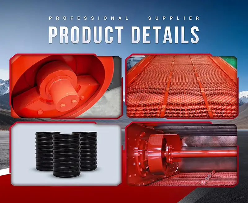
3. Vibrating Screen Bearings, Housings and Seals
Bearings in a vibrating screen operate under dynamic loading and repeated acceleration. They must also tolerate the operating conditions created by the exciter and screen structure.
Spherical roller bearings are frequently used in vibrating-screen applications because they can carry high radial loads and accommodate a degree of misalignment. However, this does not mean that every vibrating screen uses the same bearing design.
SKF’s application guidance shows that bearing selection depends on load, speed, shaft arrangement, acceleration, fit and operating clearance. Therefore, a replacement should be selected from the approved bearing designation or equipment documentation rather than bore diameter alone. See the SKF vibrating screen bearing application guidance.
Important bearing-related parts include:
Spherical roller bearing or specified alternative;
Bearing housing;
Adapter or withdrawal sleeve;
Locknut and locking washer;
Labyrinth seal;
Oil seal;
Grease fitting;
Lubrication pipe;
End cover;
Spacer and retaining components.
Common bearing warning signs
Increasing operating temperature;
Abnormal rumbling or grinding noise;
Grease or oil leakage;
Discoloured lubricant;
Excessive radial or axial play;
Damage to the housing or seal;
Repeated bearing failure after replacement.
Bearing temperature alone is not enough to confirm bearing failure. Excessive or insufficient lubrication, incorrect clearance, contamination, misalignment and drive problems can produce similar symptoms.
When ordering a bearing-related replacement, provide the full bearing designation, suffix, internal-clearance specification, housing details, seal arrangement and lubrication method.
4. Motors, Belts, Couplings and Drive Components
The drive system transfers power from the motor to the excitation system. Depending on the screen design, it may include:
Electric motor;
Motor base;
V-belts;
Drive and driven pulleys;
Flexible coupling;
Universal coupling;
Cardan shaft;
Coupling guard;
Tensioning bolts;
Mounting hardware.
A belt-driven screen requires correct pulley alignment and belt tension. A direct or cardan-shaft drive requires the correct connection dimensions, operating angle and rotation direction.
Common drive-system warning signs include:
Belt dust or polished belt surfaces;
Repeated belt breakage;
Pulley wear;
Coupling noise;
Loose motor mounts;
Abnormal shaft movement;
Burning smell;
Unstable exciter speed.
Do not change pulley diameter, motor speed or counterweight settings without verifying the original equipment design. These changes can affect vibration frequency, amplitude, bearing load and structural stress.
For replacement drive parts, record:
Motor power, voltage and speed;
Pulley outside diameter;
Shaft diameter and keyway;
Belt section and quantity;
Coupling type;
Flange and bolt dimensions;
Cardan-shaft compressed and extended length;
Existing rotation direction.
5. Springs and Vibration-Isolation Parts
Springs support the screen box and reduce the transmission of vibration to the supporting structure.
Common support components include:
Steel coil springs;
Rubber composite springs;
Rubber isolation mounts;
Spring seats;
Upper and lower mounting plates;
Retaining devices;
Support brackets.
Springs should support the machine at the intended operating height and allow controlled screen movement. Uneven spring height or stiffness can cause the screen box to sit or move unevenly.
Inspect the support system when you observe:
A broken coil;
Cracks or separation in a rubber spring;
Permanent compression;
Different unloaded heights;
Uneven movement between screen corners;
Contact between the screen box and stationary structure;
Damaged spring seats;
Loose support fasteners.
Whether one spring or an entire matched group should be replaced depends on the machine design and the condition of the remaining springs. Compare unloaded height, stiffness, position and service condition, and follow the machine manufacturer’s requirements.
The XINGAONAI Linear Vibrating Screen uses a synchronized excitation arrangement and rubber composite springs. Replacement components must therefore be matched to the relevant model rather than selected from a generic screen-parts list.
6. Screen Box, Side Plates and Cross Members
The screen box carries the deck, material load and dynamic forces generated during operation. Its principal structural parts include:
Side plates;
Cross members;
Deck frame;
Reinforcement plates;
Feed-end structure;
Discharge-end structure;
Connection brackets;
Bolts and rivets;
Support beams.
Structural components should not be treated in the same way as routine wear parts. A crack in a side plate or cross member can be associated with fatigue, loose connections, abnormal vibration, impact loading or an unsuitable repair performed previously.
Possible structural warning signs include:
Cracks around holes, corners or welded areas;
Loose or missing fasteners;
Fretting marks around connections;
Deformed cross members;
Repeated screen-media failure in the same location;
Deck movement relative to the side plate;
Uneven clearance around the screen box.
If a structural crack is found, stop the machine and determine why the crack developed. Welding without identifying the cause may only provide a temporary repair and can introduce additional stress or distortion.
Structural replacement requires accurate drawings or measurements. Provide plate thickness, material specification, hole pattern, overall dimensions and photographs showing the component’s position in the assembly.
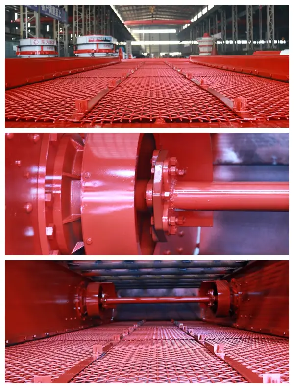
7. Feed, Discharge and Wear-Protection Parts
Material should enter the screen evenly across the usable deck width. Concentrated feeding can overload one section of the screen media and accelerate local wear.
Feed and discharge components may include:
Feed box;
Impact plate;
Rubber or steel wear liner;
Distribution plate;
Chute liner;
Skirt rubber;
Discharge lip;
Collection chute;
Spray pipes and nozzles for wet screening.
Inspect these parts when one area of the deck wears significantly faster than the others or when material accumulates against one side of the screen.
A worn feed-box liner may expose the supporting structure to direct impact. A damaged discharge lip can affect material transfer to the next conveyor or chute. Blocked spray nozzles can also create uneven washing conditions across the deck.
These components should be selected according to material size, impact, abrasiveness, moisture and the existing installation dimensions.
8. Wear Parts, Service Parts and Structural Parts
Not every component should be replaced using the same decision process.
| Part category | Examples | Recommended approach |
|---|---|---|
| Consumable wear parts | Screen media, liners, skirt rubber | Replace when wear affects fit, protection or screening performance |
| Fastening parts | Clamps, rails, bolts and panel fasteners | Inspect for looseness, deformation and thread damage |
| Service components | Bearings, seals, belts and couplings | Diagnose the operating condition and replace to the approved specification |
| Matched support parts | Springs and isolation mounts | Compare height and stiffness and follow model requirements |
| Structural parts | Side plates, beams and deck frame | Investigate fatigue, cracks and deformation before repair or replacement |
| Complete assemblies | Exciter, shaft assembly and drive unit | Confirm rotation, mounting, dimensions and operating parameters |
Avoid replacing an expensive assembly before checking the parts and operating conditions connected to it.
9. Which Part Should You Inspect First?
The following table is a starting point, not a final diagnosis.
| Operating symptom | Parts to inspect first | Additional consideration |
|---|---|---|
| Inaccurate product size | Screen media, aperture and panel fastening | Check feed distribution and screen loading |
| Screen media breaks repeatedly | Tension rails, support bars and feed-impact area | Confirm media specification and installation |
| Bearing housing becomes hot | Bearing, lubricant, seal and alignment | Check drive condition and operating clearance |
| Amplitude decreases | Exciter, drive belts, coupling and motor | Check material buildup and operating speed |
| Screen moves unevenly | Springs, mounts, exciter and structure | Compare movement on both sides |
| Metallic knocking occurs | Loose panels, fasteners, springs or drive parts | Stop the machine and locate the contact point |
| Oil or grease leaks | Seals, housing, lubrication line and breather | Confirm lubricant type and fill level |
| Structural crack appears | Side plate, cross member and connections | Investigate fatigue and abnormal vibration |
| Material accumulates on one side | Feed box, deck level and screen motion | Check whether feed enters across the full width |
For a more detailed diagnostic procedure, refer to the vibrating screen troubleshooting guide.
10. Information Required When Ordering Vibrating Screen Parts
The machine name alone is generally insufficient for accurate part identification.
Prepare the following information before requesting a quotation:
Equipment manufacturer;
Machine model;
Serial number or nameplate photograph;
Part name and part number, if available;
General arrangement or assembly drawing;
Detailed part drawing;
Overall and installation dimensions;
Mounting-hole positions;
Shaft, bore and keyway dimensions;
Rotation direction;
Screen deck position;
Screen-media aperture and fixing method;
Photographs of the complete assembly;
Close-up photographs of the worn part;
Material being processed;
Maximum feed size;
Operating capacity;
Wet or dry screening;
Required quantity;
Project location.
For screen media, add aperture shape, panel dimensions, wire diameter or panel thickness, hook type and support spacing.
For an exciter, coupling or shaft assembly, add rotation direction, connection dimensions, lubrication arrangement and photographs of both installation sides.
For springs, provide free height, outside diameter, wire diameter or rubber-spring dimensions, mounting position and the number used on the machine.
Major equipment suppliers also emphasize the importance of drawings, dimensional compatibility and complete machine identification when selecting screen and feeder spare parts. See the Metso screen and feeder spare-parts overview.
11. Parts Differ Between Vibrating Screen Designs
The term “vibrating screen” covers several machine structures.
| Screen type | Important parts difference |
|---|---|
| Circular vibrating screen | Commonly uses an eccentric shaft or exciter to generate circular motion |
| Linear vibrating screen | Uses synchronized excitation to create directional linear movement |
| High-frequency electromagnetic screen | Uses an electromagnetic excitation system rather than a conventional rotating arrangement |
| Wet screening machine | May include spray pipes, water distribution components and corrosion-resistant media |
| Heavy scalping screen | Requires strong deck supports and impact-resistant feed-area components |
The XINGAONAI Circular Vibrating Screen uses circular motion generated through an eccentric-shaft excitation system.
The Linear Vibrating Screen uses synchronized exciters to create linear movement.
The High Frequency Electromagnetic Vibrating Screen has a different excitation structure intended for fine screening.
These differences are why a photograph of the complete machine, its nameplate and the installed part is essential when an original part number is unavailable.
12. Which Vibrating Screen Spare Parts Should Be Kept in Stock?
There is no universal spare-parts inventory for every plant. Stocking decisions should consider:
Failure consequence;
Part replacement frequency;
Supplier lead time;
Number of identical machines;
Availability of local alternatives;
Installation time;
Storage conditions;
Planned production schedule.
A practical inventory can be divided into three levels.
Routine consumables
Screen panels or wire sections;
Fasteners and clamps;
Skirt rubber;
Wear liners;
Spray nozzles;
V-belts.
Planned service parts
Correct bearing and seal kits;
Lubrication components;
Coupling elements;
Spring sets;
Motor-mounting hardware.
Critical long-lead parts
Exciter assembly;
Eccentric shaft;
Gear components;
Cardan shaft;
Special pulleys;
Model-specific structural components.
Do not store bearings, rubber parts or screen media without protecting them from moisture, contamination, sunlight and deformation. Inventory should be reviewed against the inspection findings described in the vibrating screen maintenance guide.
Conclusion
Correct vibrating screen parts selection begins with accurate machine and component identification. Screen media, exciters, bearings, drive parts, springs and structural components perform different functions and require different replacement decisions.
Do not select a part from its name or approximate dimensions alone. Confirm the machine model, part number, mounting arrangement, operating parameters and available drawings. When a failure repeats, investigate the connected components and operating conditions instead of replacing the same visible part again.
To request a replacement-parts evaluation, send XINGAONAI the equipment model, nameplate, photographs, available drawings, component dimensions, material information and required quantity. The information will be reviewed for part identification and dimensional compatibility before quotation.