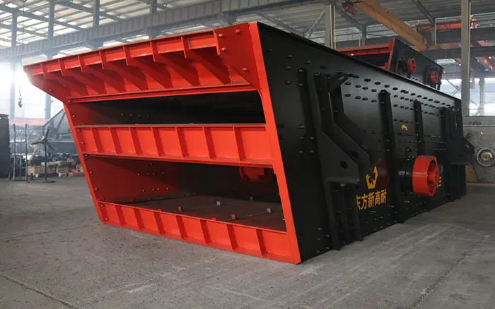
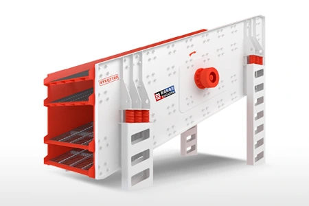
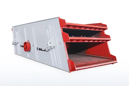
A vibrating screen deck is the screening level that supports the screen media and carries material through the separation process. Selecting the correct deck involves more than choosing an aperture size. The number of decks, feed distribution, required products, material moisture, abrasiveness, screen media and maintenance access must be considered together.
A screen with the correct nominal capacity can still perform poorly if the deck is overloaded, the media does not suit the material or the feed is concentrated on only part of the screening surface. Conversely, a correctly configured deck helps distribute material evenly, maintain product-size control and reduce unnecessary media replacement.
This guide explains the difference between a screen deck and screen media, compares single-, double- and multi-deck configurations, and provides a practical process for selecting deck materials and arrangements.
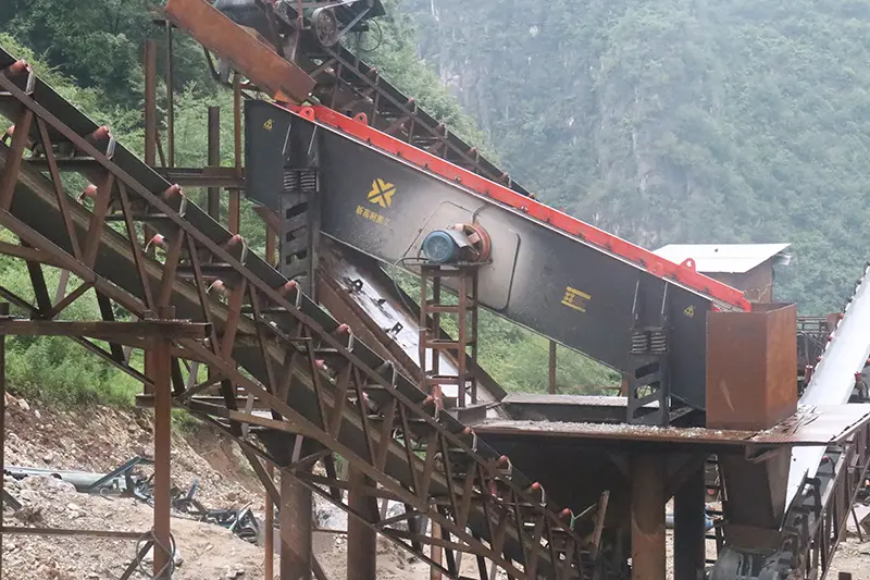
What Is a Vibrating Screen Deck?
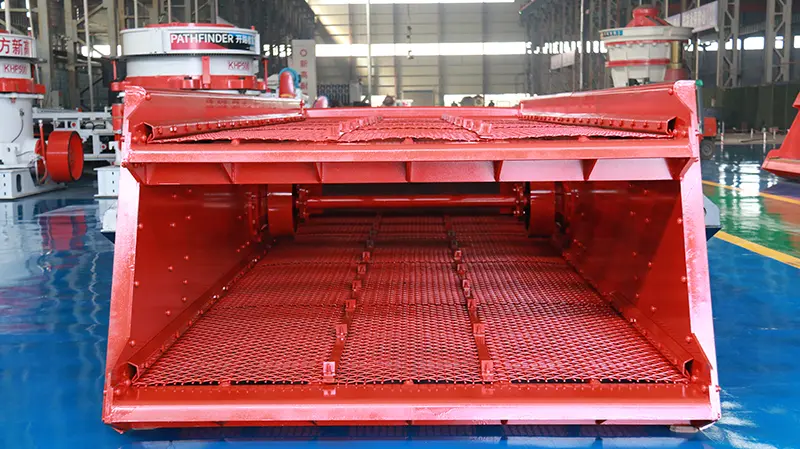
A vibrating screen deck is one screening level installed inside the screen box. It supports the screening media and provides the surface over which material travels.
Three terms are commonly confused:
| Term | Meaning |
|---|---|
| Screen deck | The complete screening level that supports the media and carries material |
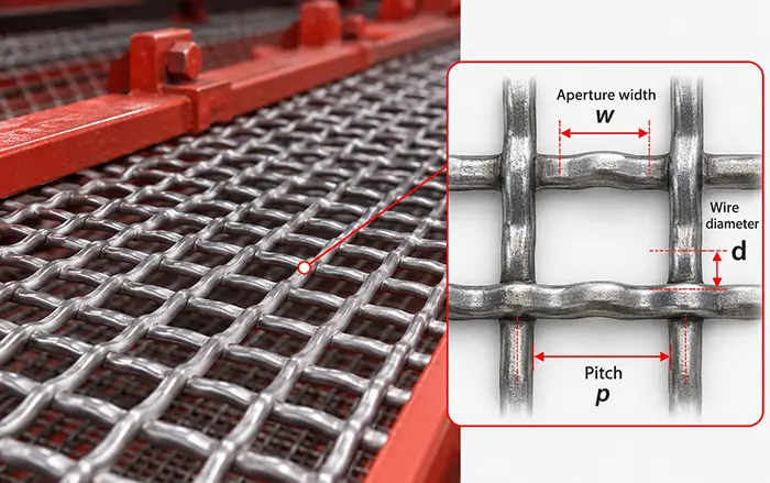
| Screen media | The replaceable wire mesh, rubber panel, polyurethane panel or perforated plate through which particles are separated |
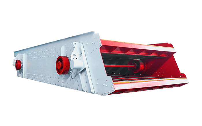
| Screen box | The main vibrating structure containing the decks, side plates, cross members and discharge sections |
In practice, the word “deck” is sometimes used to describe only the replaceable screening surface. For equipment selection, however, the complete deck also includes its support structure, fastening system, media layout and discharge arrangement.
The screen deck must withstand material impact, vibration and continuous abrasive contact while maintaining the correct surface shape and media tension.
Single-, Double- and Multi-Deck Vibrating Screens
The number of decks determines how many separation cuts can be completed inside one screen box.
A single deck makes one separation cut and can normally produce up to two material streams. A double deck makes two cuts and can produce up to three streams. A triple deck can make three cuts and produce up to four streams.
This relationship applies only when the discharge streams remain separate. If some streams are recombined in the plant flowsheet, the number of final products will be lower.
| Configuration | Separation cuts | Maximum separate streams | Typical use |
|---|---|---|---|
| Single deck | 1 | 2 | Oversize and undersize separation |
| Double deck | 2 | 3 | Coarse, intermediate and fine products |
| Triple deck | 3 | 4 | Multiple aggregate specifications |
| Four or more decks | 4+ | 5+ | Special multi-product classification |
A single deck vibrating screen is usually sufficient when the process requires only one controlled cut.
A double deck vibrating screen is more suitable when a single feed must be divided into three separate fractions.
Adding more decks does not automatically increase total capacity. Lower decks receive the material passing through the upper decks and may become the limiting stage when the feed contains a high percentage of fines or near-size particles.
Main Types of Vibrating Screen Media
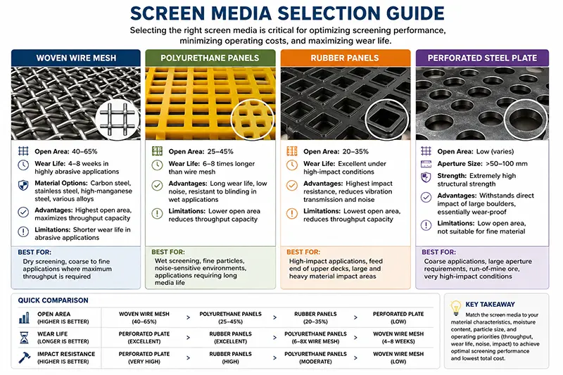
The screen deck provides the supporting structure, while the screen media performs the actual particle separation. The media must be selected according to the feed size, target cut, moisture, impact load, abrasiveness and maintenance requirements.
Industry suppliers commonly classify vibrating screen media into woven wire, polyurethane, rubber and rigid plate systems. Material alone is not enough to determine performance; aperture geometry, open area, fastening and deck support must also be considered. This is consistent with the selection factors described in Polydeck’s screening media guide.
Woven Wire Screen Media
Woven wire screen media is widely used in aggregate and mineral classification because it provides relatively high open area and allows a wide range of aperture sizes.
It can be considered when:
The material is dry or contains limited moisture
High open area is required
The feed impact is within the wire’s design range
Screen openings need to be changed relatively easily
Operators can regularly inspect wire tension and breakage
Woven wire may lose tension, break or wear unevenly under severe impact and abrasive conditions. Improper tension can allow the media to move against its supports, accelerating fatigue and reducing separation accuracy.
Different wire profiles and opening shapes are available, but the final aperture should be determined from actual product specifications and feed characteristics.
Polyurethane Screen Panels
Polyurethane panels are commonly evaluated for wet screening, fine classification, dewatering and abrasive applications.
Their potential advantages include:
Good abrasion resistance
Modular replacement
Compatibility with wet screening
Different aperture shapes within one panel system
Reduced noise compared with steel media
Polyurethane panels generally have thicker borders than woven wire. Depending on the panel design, this can reduce open area, so the required screening area must be checked instead of assuming that panels with the same aperture will deliver the same capacity.
Rubber Screen Panels
Rubber panels are frequently used where the feed produces high impact or where noise reduction is important.
They may be considered for:
Coarse aggregate screening
High-impact feed zones
Abrasive material
Applications requiring lower operating noise
Deck sections experiencing concentrated wear
Rubber media is not automatically suitable for every wet, sticky or fine-screening application. Aperture flexibility, panel thickness and available open area must still be evaluated.
Perforated Plate and Bar Decks
Perforated steel plate, punch plate and bar-type surfaces are mainly considered for coarse screening and scalping duties.
They may be used when:
Large feed particles create high impact
Fine separation accuracy is not the main objective
Oversize must be removed before crushing
Strong deck support is required
Conventional woven wire would be damaged too quickly
These rigid surfaces generally provide lower open area than fine woven media but can tolerate heavier feed in appropriate applications.
How Deck Design Affects Screening Performance
A vibrating screen deck should be evaluated as a complete system. Aperture size is important, but several other deck characteristics determine whether particles have a realistic opportunity to pass through the openings.
Effective Screening Area
The nominal length and width do not always equal the usable screening area. Side clamping, panel borders, deck supports and blank sections reduce the surface available for particle passage.
When comparing two media systems, check both total deck area and effective open area.
Feed Distribution
Material should enter across as much of the usable deck width as practical. A narrow feed stream overloads one section while leaving the rest of the deck underused.
Uneven feeding can cause:
Localized media wear
Excessive bed depth
Material carryover
Reduced screening accuracy
Uneven loading of deck supports
Feed-box and chute design therefore affect deck performance even though they are not part of the replaceable screen media.
Material Bed Depth
Particles must reach the deck surface before they can pass through an opening. If the material bed is too deep, fines can remain trapped under larger particles and leave with the oversize stream.
Bed depth is influenced by feed rate, deck width, inclination, motion, material flowability and the percentage of near-size particles.
Aperture and Open Area
The aperture determines which particles may pass, while open area affects how many passing opportunities are available.
Selecting an opening only from the required product size can produce an incorrect result because particle shape, moisture, wear and opening geometry influence the practical separation point.
For a focused selection process, see the guide to vibrating screen aperture size.
Deck Inclination and Screen Motion
Inclination and vibration affect material travel speed, stratification and residence time. A steeper surface may move material faster, but shorter residence time can reduce passing opportunities in some conditions.
The selected angle cannot be separated from the machine’s motion, amplitude, frequency and feed characteristics. These settings should follow the equipment design rather than being copied from another screen.
For the separation process itself, see the vibrating screen working principle.
Media Fastening and Support
Screen media must remain properly supported and tensioned. Loose media can move against cross members, damage fastening components and produce uncontrolled openings.
Common fastening systems include:
Hooked tensioned wire
Pressure plates and bolts
Modular snap-in panels
Pin-and-sleeve systems
Bolt-down rubber or polyurethane panels
Metso’s overview of screening media tension systems also emphasizes that media type and fastening method should be selected as one system.
How to Select a Vibrating Screen Deck
The selection process should begin with the required products, not with a screen model or media material.
Step 1: Define the Required Products
List every required product size and identify whether each stream must remain separate.
For example, a plant that requires:
Larger than 20 mm
10–20 mm
5–10 mm
Smaller than 5 mm
requires at least three separation cuts. This could be completed with a suitable triple-deck screen or through several screens arranged within the process.
The final choice depends on capacity, installation height, maintenance access and material routing.
Step 2: Analyse the Feed
Provide the equipment supplier with:
Material name
Maximum feed size
Complete particle-size distribution
Bulk density
Moisture content
Clay content
Particle shape
Abrasiveness
Percentage of material near each cut size
Maximum feed size and total capacity alone are not enough. Two feeds with the same maximum particle size can produce very different deck loads if one contains considerably more fine material.
Step 3: Determine the Load on Each Deck
Each deck should be checked separately.
The upper deck receives the complete feed, but it may remove a large proportion of coarse material quickly. The lower deck receives only material that passes through the upper deck, but it may carry a much higher percentage of fines and near-size particles.
For that reason, the lowest deck can become the capacity or efficiency bottleneck even when the total screen appears large enough.
Step 4: Select the Screen Media
Use the material conditions as a starting point:
| Operating condition | Media to evaluate first | Main reason |
|---|---|---|
| Clean, dry aggregate | Woven wire | High open area and flexible aperture options |
| Wet, abrasive fine material | Polyurethane | Wear resistance and wet-screening suitability |
| Coarse, high-impact feed | Rubber or heavy-duty plate | Impact absorption and durability |
| Sticky material prone to blinding | Flexible or self-cleaning media | Greater resistance to blocked openings |
| Scalping before a crusher | Bar deck or perforated plate | Strength under coarse feed impact |
| Frequent specification changes | Modular panels or replaceable wire sections | Easier media replacement |
These are starting points rather than universal rules. The final selection should be checked against the screen structure and actual material behaviour.
Step 5: Check Fastening and Maintenance Access
A suitable screen media material can still be a poor choice if it is difficult to install, tension or inspect.
Check:
Space above and below each deck
Access to side tensioning bolts
Clearance for panel removal
Cross-member condition
Compatibility with existing support rails
Time required to isolate and open the screen
Availability of replacement panels or wire sections
Multi-deck screens require particular attention because access to the lower deck is more restricted.
Step 6: Confirm the Complete Machine Configuration
Deck selection must be coordinated with the complete vibrating screen.
Depending on the required motion and application, users may consider the YKQ Series Circular Vibrating Screen for inclined aggregate classification or the YKZ Series Linear Vibrating Screen for applications suited to linear motion.
Neither design is universally better. The correct option depends on the feed, target products, plant layout and required screening duty.
Engineering Example: 300–350 TPH Aggregate Plant
A 300–350 t/h stone crushing plant provides a practical example of how vibrating screen deck configuration can be matched to plant capacity and final aggregate specifications.
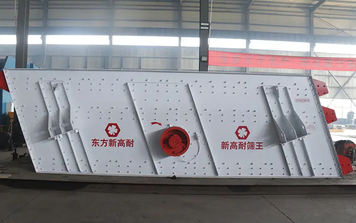
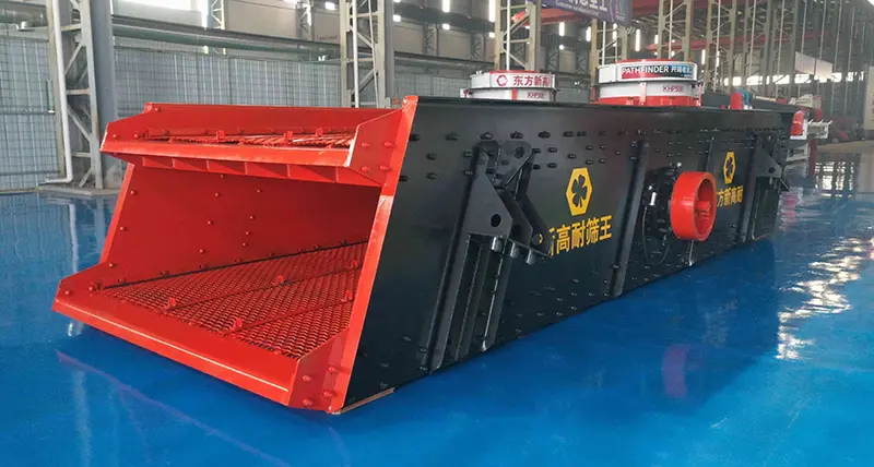
The engineering configuration includes three 2YKZ2470 double-deck vibrating screens. Each unit has a 2,400 × 7,000 mm screening surface, providing 16.8 m² per deck and 33.6 m² across two decks.
The screening section is designed to separate crushed material into four final size ranges:
0–5 mm
5–10 mm
10–20 mm
20–30 mm
The screen configuration is:
| Specification | Project configuration |
|---|---|
| Screen model | 2YKZ2470 |
| Number of screens | 3 |
| Deck configuration | Double deck |
| Screen surface | 2,400 × 7,000 mm |
| Screen area | 2 × 16.8 m² per screen |
| Recommended feed size | 0–80 mm |
| Rated capacity | 200–300 t/h per screen |
| Installation angle | 20° |
| Vibration frequency | 960 times/min |
| Double amplitude | 6–9 mm |
| Motor power | 30 kW per screen |
| Screen media | 65Mn steel wave screen |
| Media fastening | Steel pressure plate with bolt fixing |
The three screens are incorporated into the production flowsheet to provide the screening area and separation stages required for the four final products. The complete plant configuration—not one individual double-deck screen—produces the four specified size ranges.
The specified 65Mn steel wave screen is secured using steel pressure plates and bolts. This fastening arrangement keeps the media installed against the deck supports while allowing worn sections to be removed during maintenance.
This configuration also demonstrates why total plant capacity should not be used as the only screen-selection value. The following must be evaluated together:
Number of required final products
Load reaching each screening stage
Particle-size distribution
Available screening area
Screen aperture arrangement
Media material and fastening
Conveyor and chute routing
The figures above are equipment configuration values rather than guaranteed site-performance results. Actual capacity and separation efficiency depend on feed gradation, moisture, particle shape, near-size content and operating conditions.
Common Vibrating Screen Deck Problems
Deck problems often appear as product-quality or capacity problems before visible structural damage is found.
| Problem | Possible deck-related causes | Initial inspection |
|---|---|---|
| Blinding | Wet fines, clay, unsuitable media or insufficient deck movement | Inspect whether apertures are coated or covered |
| Pegging | Particles close to the aperture size becoming trapped | Check opening shape and near-size content |
| Uneven media wear | Off-centre feed, uneven bed depth or damaged support | Compare wear across the deck width |
| Broken wire | Excessive impact, fatigue, poor tension or contact with supports | Inspect feed zone, tension and support bars |
| Loose panels | Failed fasteners, worn rails or incorrect installation | Check all fastening points after isolation |
| Material carryover | Excessive deck load, low open area or insufficient passing opportunity | Check feed rate, bed depth and media condition |
| Product contamination | Torn media, open panel joints or blocked discharge chute | Inspect deck surface and each discharge path |
Operators should not adjust or inspect the screen while it is running. The machine must be isolated according to the site’s lockout and safety procedures before entering or working around the screen box.
For a more detailed fault-diagnosis process, refer to vibrating screen troubleshooting.
Information Required for Screen Deck Selection
Before requesting a screen recommendation, prepare the following information:
Material name and source
Maximum feed size
Complete feed particle-size distribution
Required plant capacity in t/h
Required final product sizes
Number of separate products
Bulk density
Moisture and clay content
Dry or wet screening
Abrasiveness and feed impact
Percentage of near-size particles
Operating hours per day
Existing screen dimensions, if replacing media
Existing fastening and support system
Available installation space
Project location and power supply
For an existing screen, also provide photographs of the complete deck, side fastening, support rails, worn media and equipment nameplate. Deck dimensions alone do not confirm that another media system will fit.
Conclusion
The correct vibrating screen deck is not simply the deck with the largest area or the most wear-resistant media. It is the configuration that provides sufficient passing opportunities, maintains suitable material distribution and produces the required products under the actual feed conditions.
Begin with the required final sizes, determine the necessary separation cuts and calculate the load reaching each deck. Then select screen media, aperture, fastening and maintenance access as one complete system.
For a screen recommendation, provide your material, maximum feed size, complete gradation, target capacity, final product sizes, moisture and project location. XINGAONAI can use this information to evaluate the required deck configuration and complete vibrating screen model.