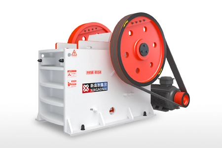
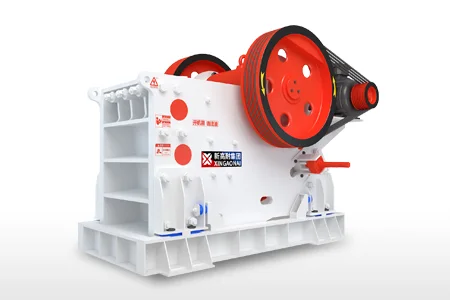
Jaw crusher balancing involves more than checking whether a flywheel rotates smoothly. The flywheel, pulley, counterweights, eccentric shaft and moving jaw work as a connected mechanical system. Their installation and condition influence how forces reach the bearings, frame and foundation.
Some vibration is inherent in a machine that uses reciprocating motion to crush rock. However, a sudden increase in vibration, visible flywheel wobble or repeated loosening of fasteners requires investigation.
Before arranging jaw crusher flywheel balancing, determine whether the problem comes from mass imbalance, incorrect counterweight installation, drive misalignment, damaged bearings, loose supports or unstable material flow. Each cause requires a different correction.
This guide explains what to inspect, how to interpret the evidence and when replacement parts or specialist balancing assessment may be required.
Safety: Stop, isolate and lock out the crusher before inspecting rotating components. Flywheels and moving assemblies can retain mechanical energy after the power supply is disconnected. Follow the model-specific procedure for securing the mechanism and handling heavy components.
1. What Does Jaw Crusher Balancing Mean?
The word “balancing” is often used to describe several different conditions.
| Term | What it means | What must be checked |
|---|---|---|
| Flywheel mass balance | Distribution of mass around the rotational axis | Condition, approved geometry and residual unbalance specification |
| Counterweight positioning | Angular relationship between counterweights and the moving mechanism | Assembly drawings, identification marks and installation orientation |
| Drive alignment | Relationship between the motor pulley and crusher pulley | Pulley alignment, belt condition and shaft mounting |
| Installation stability | How the crusher is supported and secured | Foundation, grout, anchors, frame connections and approved isolation elements |
A flywheel that has been balanced separately does not guarantee satisfactory vibration after installation. Shaft fit, assembly orientation, counterweight configuration and support conditions still matter.
Some components incorporate intentional eccentric mass to compensate for part of the mechanism’s inertia. Removing that mass to make an individual component appear evenly balanced can interfere with the machine’s intended operation.
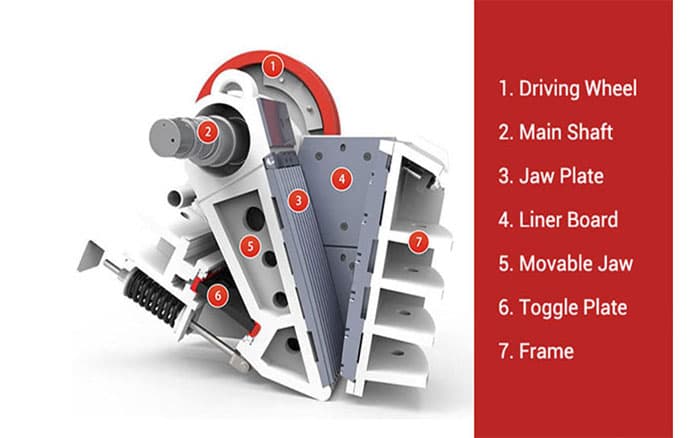
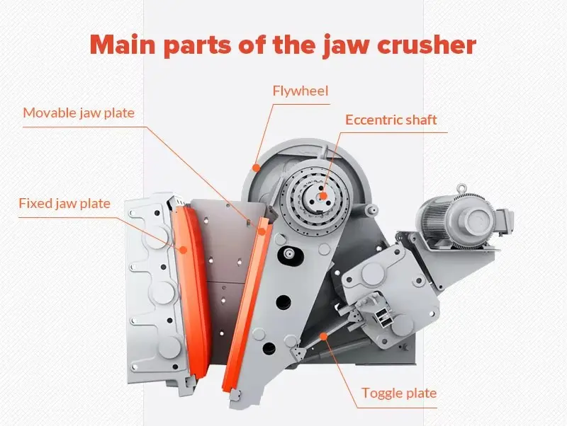
For the relationship between the shaft, moving jaw and drive components, see our jaw crusher parts and functions guide.
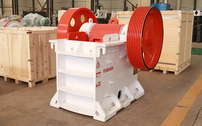
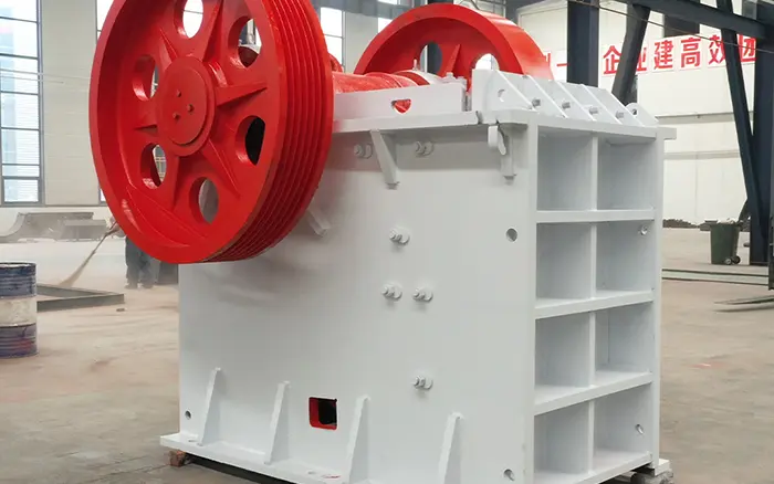
2. How the Flywheel and Counterweights Work
The motor transfers power through the drive system to the eccentric shaft. The shaft produces the moving jaw’s repeated crushing motion.
Crushing resistance changes throughout each cycle. The flywheel stores rotational energy and releases it as the load rises, helping reduce speed fluctuation.
Counterweights serve a related but different purpose: their mass and angular position help manage the inertia forces generated by the mechanism. The required arrangement depends on the crusher design.
This means that the following are separate checks:
Whether the flywheel has the specified geometry and mass distribution;
Whether the counterweights match the model;
Whether the components are installed in the correct angular relationship;
Whether the wheel is properly secured to the shaft;
Whether the complete drive and supporting structure are sound.
Do not transfer counterweight positions or correction masses from another crusher, even when the machines have similar feed openings.
3. Normal Vibration vs Abnormal Flywheel Imbalance
The most useful comparison is with the crusher’s own condition when operating correctly.
Measurements should be compared at the same location, direction, speed, load and instrument settings. A reading taken on the foundation cannot be compared directly with one taken on a bearing housing.
Warning signs include:
Vibration increasing immediately after flywheel or shaft work;
New vibration during permitted no-load operation;
Visible radial or axial flywheel wobble;
Knocking around the hub or shaft connection;
Counterweights or fasteners becoming loose;
Repeated belt tracking problems;
Increasing vibration accompanied by bearing heat or noise;
Recurrent anchor-bolt loosening;
A marked change between the two sides of the crusher.
These signs justify inspection, but none alone proves mass imbalance.
A visible wobble may indicate runout, poor seating, a worn bore or shaft damage. Adding balancing weight will not correct those defects.
4. Common Causes of Apparent Jaw Crusher Imbalance
| Possible cause | Typical clue | First check |
|---|---|---|
| Material buildup on the wheel | Vibration changes after cleaning | Inspect the rim, recesses and belt grooves |
| Loose counterweight or mounting | New knocking or changed movement | Check attachment condition and assembly marks |
| Incorrect counterweight orientation | Problem starts after disassembly | Compare with the exact assembly drawing |
| Flywheel runout | Visible wobble or unstable belt travel | Measure radial and axial runout |
| Worn key, keyway or hub fit | Knocking during start or stop | Inspect the shaft connection |
| Pulley misalignment | Belt-edge wear, heat or tracking problems | Check the motor and crusher pulleys |
| Incorrect belt condition or tension | Slapping, slipping or unequal load sharing | Inspect the complete belt set |
| Shaft or bearing damage | Vibration persists after wheel checks | Inspect journals, bearings, fits and lubrication |
| Loose frame or foundation | Movement around anchors or connections | Inspect the support and mounting system |
| Uneven feed or blocked discharge | Problem mainly occurs under load | Check material distribution and downstream flow |
| Structural resonance | Strong response within a speed range | Obtain a vibration and structural assessment |
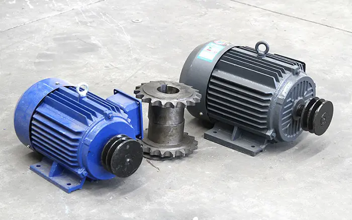
The drive should be evaluated as a complete system. Our jaw crusher motor and drive guide explains the relationship between motor selection, transmission and operating load.
5. Diagnose the Source Before Changing Balance Weights
Step 1: Establish when the problem started
Record whether vibration appeared after:
Flywheel replacement;
Bearing or eccentric-shaft work;
Belt replacement;
Motor repositioning;
Foundation repair;
A blockage or abnormal crushing event;
A gradual deterioration over several weeks.
A problem that begins immediately after maintenance should first be checked against the work performed.
Step 2: Compare operating conditions
Where the manufacturer permits it, qualified personnel may compare controlled no-load and loaded operation with all guards in place.
If vibration exists under both conditions, inspect rotating components, drive alignment, bearings and supports.
If the change is mainly load-related, investigate uneven feeding, bridging, packing, discharge restrictions and changing material properties.
A strong response at a particular speed may involve imbalance, structural resonance or another speed-dependent excitation. It requires further diagnosis.
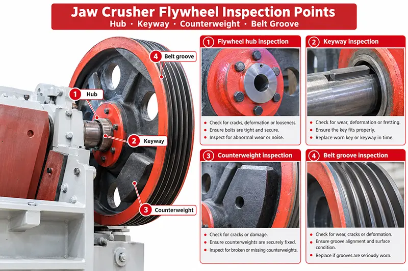
Step 3: Inspect the stopped machine
After isolation and mechanical securing, inspect:
Material buildup;
Loose or missing fasteners;
Counterweight identification and position;
Hub, spoke and rim cracks;
Shaft keys and keyways;
Locking assemblies or clamping connections;
Belt grooves;
Signs of contact with guards;
Bearing housings and frame connections.
Compare assembly marks with the correct drawing. Do not assume marks from a previous repair are accurate.
Step 4: Check geometry and alignment
Qualified maintenance personnel should check pulley alignment, wheel seating, radial runout, axial runout and shaft condition against the applicable limits.
Runout and mass imbalance are different. A geometrically incorrect installation should be corrected before considering balance correction.
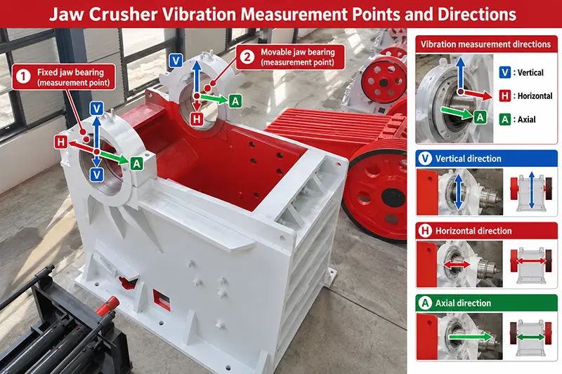
Step 5: Collect comparable vibration data
Record:
Measurement location;
Horizontal, vertical or axial direction;
Actual crusher speed;
No-load or loaded state;
Feed conditions;
Instrument bandwidth and settings;
Velocity, acceleration or displacement units;
RMS, peak or peak-to-peak convention;
Frequency spectrum;
Phase information where available.
6. What Evidence Supports a Flywheel Imbalance Diagnosis?
A component at once-per-revolution frequency, commonly called 1× running speed, can support an imbalance investigation. However, a jaw crusher also generates forces from its reciprocating mechanism and crushing process.
A 1× peak alone is not sufficient evidence for adding weight.
A stronger diagnosis combines:
Repeatable vibration measurements;
Stable phase information where relevant;
Verified operating speed;
A clear maintenance history;
Correct wheel mounting and counterweight orientation;
Acceptable runout and shaft condition;
Checks excluding loose connections, bearing damage and foundation problems.
The decision should consider the complete machine response. A reduction in one measurement direction is not an acceptable result if another location becomes significantly worse.
7. Choose the Correction That Matches the Fault
| Finding | Appropriate response |
|---|---|
| Removable material buildup | Clean, inspect and remeasure under comparable conditions |
| Loose connection without component damage | Restore the connection according to the approved procedure |
| Incorrect assembly orientation | Reinstall using the model-specific drawing |
| Misaligned pulleys | Correct alignment and verify belt condition |
| Damaged key, keyway or hub | Assess and replace the affected compatible components |
| Cracked or deformed flywheel | Remove from service pending an engineering assessment |
| Bent shaft or damaged journal | Assess the shaft and associated bearings |
| Confirmed residual imbalance | Arrange an approved balancing procedure |
| Loose foundation or damaged support | Repair the support system before assessing balance |
| Uneven feed or restricted discharge | Correct material flow and repeat the assessment |
Do not use extra weight to hide a worn shaft connection, cracked wheel or loose foundation.
8. Reinstallation, Static Balance, Dynamic Balance and Field Balancing
Reinstallation
Reinstallation may resolve a problem caused by incorrect seating, mismatched assembly marks or wrong counterweight orientation. It must follow the correct drawing and shaft-connection procedure.
Static balance
Static balancing evaluates resultant mass eccentricity. It does not establish that the complete crusher mechanism has the correct counterweight relationship or that a rotating assembly has no couple unbalance.
For components designed with intentional eccentric mass, the acceptance requirement must come from the component drawing.
Dynamic balance
Dynamic balancing evaluates unbalance while the component rotates. The required correction planes, assembly condition and acceptance criteria depend on the component and its intended use.
ISO 21940-11 covers procedures and tolerances for rotors with rigid behaviour. Its use requires an appropriate engineering specification; the standard’s existence does not establish one universal balance grade for all jaw crushers.
Field balancing
Field balancing assesses the rotating assembly in its installed condition. It requires suitable instruments, a controlled procedure and qualified personnel.
ISO 21940-13 addresses criteria and safeguards for in-situ balancing of medium and large rotors.
Do not weld on trial weights, drill the wheel or move counterweights through trial and error. Any correction requires approval for the particular component and secure attachment arrangements.
9. When Should a Flywheel Be Replaced?
Replacement may be necessary when inspection identifies:
Cracks in the hub, spokes or rim;
A substantially damaged keyway or bore;
Worn belt grooves beyond the approved limit;
Deformation after impact;
Runout that cannot be corrected through proper mounting;
Unapproved welding or machining that compromises integrity;
Damage making an approved repair impractical.
Surface dirt or light corrosion alone does not establish the need for replacement. Condition, dimensions and structural integrity must be assessed.
For XINGAONAI equipment, confirm the exact PE Series Jaw Crusher or PEV Series Jaw Crusher model before requesting replacement components.
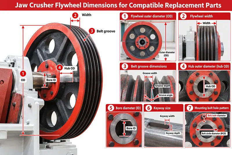
10. Information Required for Replacement Parts
Provide:
Manufacturer, model and serial number;
Nameplate photograph;
Part number and assembly drawing;
Flywheel outside diameter, width and hub dimensions;
Shaft bore and keyway dimensions;
Belt-groove profile and quantity;
Counterweight identification and arrangement;
Shaft-connection or locking-assembly details;
Rotation direction and actual operating speed;
Motor power;
Photographs of both sides and the damaged area;
Existing assembly marks;
Description of when vibration started;
Available vibration and runout records;
Required quantity and project location.
Similar appearance and nominal machine size do not confirm compatibility.
11. Prevent Repeated Balancing Problems
Keep wheels and grooves clean, preserve assembly marks and record counterweight positions before disassembly.
Check shaft connections, fasteners, pulley alignment and belt condition according to the model’s maintenance requirements. Use matched belt sets where specified and avoid changing speed or counterweights without approval.
After major work, compare vibration at the same measuring points and operating conditions. Keep the readings with the machine’s maintenance record.
Also maintain even feeding and unrestricted discharge. A balanced rotating assembly cannot compensate for an unstable crushing process or a loose support structure.
Conclusion
Jaw crusher vibration should be diagnosed before counterweights are changed. Begin with the maintenance history, wheel condition, mounting, alignment, bearings, foundation and material flow. Use comparable measurements to determine whether imbalance remains a credible cause.
XINGAONAI supplies jaw crushers and replacement components. For a parts enquiry, send the model, serial number, drawings, dimensions, photographs and inspection findings so the required components and compatibility can be reviewed before quotation.