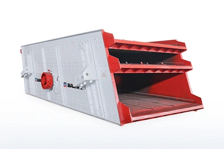
The screen aperture is one of the most important parameters affecting particle-size separation. However, choosing an aperture is not as simple as matching the opening directly to the required product size.
A nominal 10 mm opening does not necessarily produce a precise 10 mm cut. The actual separation result also depends on screen inclination, screen media thickness, aperture shape, particle shape, moisture, the percentage of near-size particles, open area, bed depth and material distribution.
Before changing the aperture, it is helpful to understand how a vibrating screen works. Screening depends on stratification and repeated contact between particles and the screen surface. A particle can pass only when it reaches an opening in a suitable orientation.
This guide explains how to define, compare, select, measure and adjust vibrating screen aperture size without treating the opening as an isolated parameter.
What Does Screen Aperture Mean?
Screen aperture is the clear opening through which particles may pass. It does not include the wire, bar or solid section surrounding the opening.
The way aperture size is stated depends on the shape and construction of the screen media.
Square openings
A square opening is normally specified by the clear distance between two adjacent wires in both directions.
For example:
10 × 10 mm means a clear opening 10 mm wide and 10 mm long.
The wire diameter is not included in the stated aperture.
A complete specification should also state the wire diameter and material.
Rectangular or slotted openings
A slotted opening is stated using two dimensions, such as 5 × 20 mm.
The orientation of the slot relative to material flow must also be specified. Slots running parallel to the flow may behave differently from slots running across it, especially when the feed contains elongated or flaky particles.
Round openings
A round opening is specified by its clear diameter. A 10 mm round opening should not be assumed to give the same separation result or open area as a 10 mm square opening.
Molded polyurethane or rubber openings
Polyurethane and rubber panels may use tapered openings. In this case, confirm whether the stated dimension refers to:
The top opening;
The narrowest throat;
The bottom opening;
Or the manufacturer’s nominal aperture.
This distinction becomes important when comparing molded panels with woven wire mesh.
Screen Aperture vs Mesh Size vs Wire Diameter
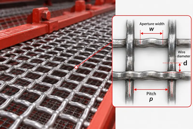
Screen aperture, mesh count and wire diameter describe different characteristics.
| Term | Meaning |
|---|---|
| Screen aperture | Clear space available for a particle to pass through |
| Mesh count | Number of openings per linear inch |
| Wire diameter | Thickness of the wire forming the opening |
| Pitch | Distance from the centre of one wire to the centre of the next |
| Open area | Percentage of the total screen surface occupied by openings |
| Cut size | Particle size at which the feed is separated in actual operation |
For regular square woven wire mesh:
Pitch:
p = w + d
Where:
p= pitch;w= clear aperture;d= wire diameter.
If the dimensions are in millimetres, an approximate mesh count can be calculated as:
Mesh ≈ 25.4 ÷ (w + d)
Mesh count alone is therefore not sufficient. Two meshes can have the same mesh count but different clear openings if their wire diameters are different.
For mining, aggregate and industrial screening, it is normally clearer to specify:
Aperture in mm + wire diameter + material + weave or panel type
Why Nominal Aperture Is Not the Same as Actual Separation Size
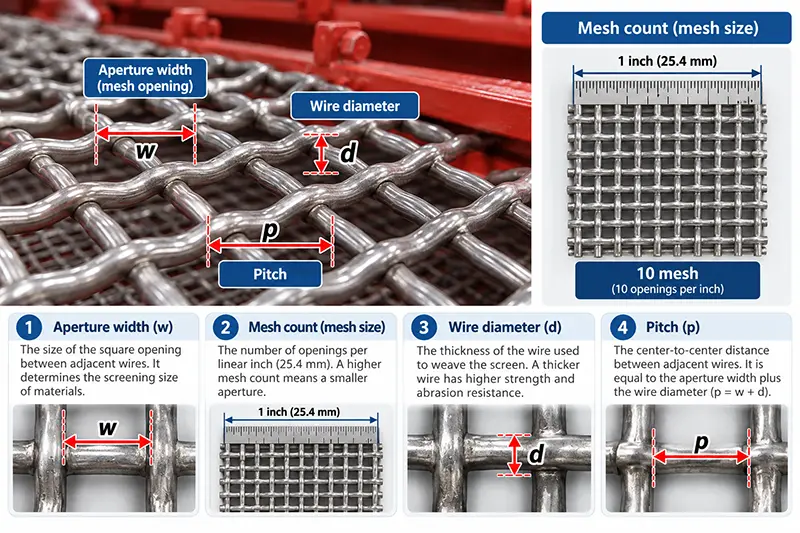
The nominal aperture is a physical dimension of the screen media. The actual cut size is the separation result produced under operating conditions.
Several factors create a difference between them.
Screen inclination
On an inclined deck, particles approach an opening at an angle. The projected opening available to the particle may be smaller than the nominal opening measured perpendicular to the screen surface.
Screen media thickness
A thick polyurethane or rubber panel creates a deeper passage than a thin wire mesh. Even when the top openings have the same dimension, a thicker passage can restrict particles that do not approach at a suitable angle.
Aperture shape
Square, slotted, round and tapered openings offer different passage geometry. They should not be treated as interchangeable based only on one nominal dimension.
Particle shape
Rounded or cubical particles behave differently from flaky and elongated particles. An elongated particle may pass through a slot or square opening when aligned with its narrow dimension, even though its length is greater than the nominal aperture.
Number of presentation opportunities
Particles do not pass immediately when they enter the screen. They must first stratify through the material bed and make repeated contact with the screen media. Excessive bed depth, uneven feeding or insufficient deck length reduces these opportunities.
Blinding, pegging and wear
Blocked openings reduce the effective aperture and open area. Worn or torn openings can allow oversized particles to pass.
Why Open Area Matters
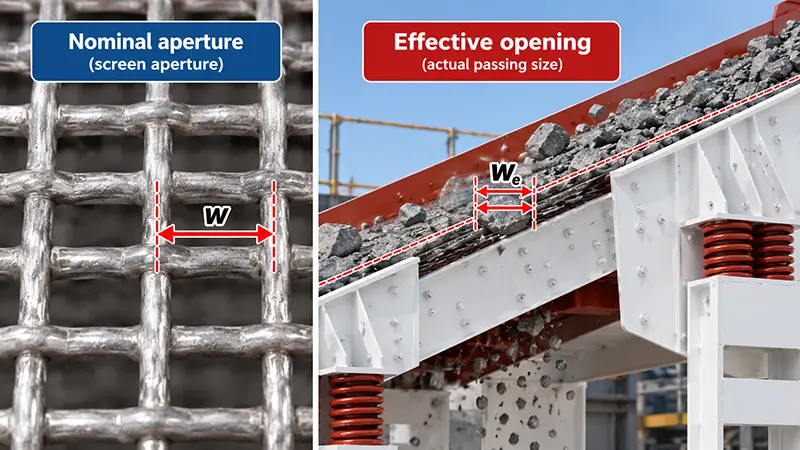
Open area is the proportion of the screen surface through which material can theoretically pass.
For square woven wire mesh:
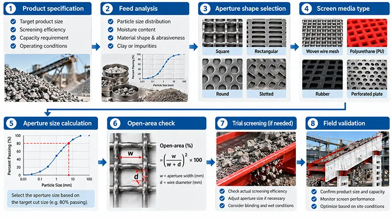
Open area (%) = 100 × [w ÷ (w + d)]²
Where:
w= clear aperture;d= wire diameter.
Consider two screen meshes with the same 10 mm aperture:
10 mm aperture with 2 mm wire
Open area = 100 × [10 ÷ (10 + 2)]²
Open area ≈ 69.4%
10 mm aperture with 4 mm wire
Open area = 100 × [10 ÷ (10 + 4)]²
Open area ≈ 51.0%
Both are described as 10 mm screens, but the first provides substantially more passage area.
Higher open area can improve throughput and particle presentation. However, it can also mean thinner wires, lower impact resistance or shorter wear life. Screen selection must balance:
Capacity;
Separation accuracy;
Wear life;
Impact loading;
Blinding risk;
Replacement frequency;
And total operating cost.
Open area is only one of the factors affecting vibrating screen efficiency.
Choosing the Right Aperture Shape
Square apertures
Square openings are the standard choice for general classification and usually provide predictable sizing for relatively cubical particles.
Advantages:
Clear and familiar specification;
Suitable for most dry aggregate and mineral applications;
Good balance between accuracy and capacity.
Limitations:
Near-size particles can become pegged;
Elongated particles may pass in certain orientations;
Fine wet material may blind the openings.
Slotted apertures
Slotted openings can increase open area and throughput. They may also reduce pegging when the slot dimensions and orientation are selected correctly.
They are useful for:
Elongated particles;
High-capacity classification;
Some dewatering applications;
Material containing a large percentage of near-size particles.
Their main limitation is that long or flaky particles may pass through the slot and contaminate the undersize product. The slot direction relative to material flow should always be specified.
Round apertures
Round holes are commonly used in perforated plate and heavy-duty screening surfaces. They provide a robust structure and can be suitable for coarse or impact-intensive applications.
A round opening should not be substituted directly for a square opening of the same stated size without testing the product distribution and open area.
Tapered apertures
Tapered openings are common in molded polyurethane and rubber media. The widening passage can help particles release after entering the opening.
Tapered openings can reduce some types of pegging, but they cannot compensate for poor feed distribution, excessive moisture or an unsuitable aperture size.
Self-cleaning media
Self-cleaning wire media can be useful for sticky, irregular or difficult-to-screen feeds. Its flexible wires reduce the tendency of near-size particles to remain trapped.
Before using it, confirm that the media can withstand the impact load, particle size and structural support arrangement.
How to Choose the Correct Vibrating Screen Aperture Size
Step 1: Define the product specification
Do not start by asking only, “What opening should I use?”
First define what the finished product must achieve:
Maximum acceptable size in the undersize product;
Minimum acceptable size in the oversize product;
Allowed contamination or misplaced material;
Required aggregate fraction;
Downstream crusher or mill feed requirement;
Whether the duty is sizing, scalping, desliming or dewatering.
A narrow product tolerance requires a more controlled screening arrangement than a rough scalping duty.
Step 2: Analyse the complete feed size distribution
Obtain a representative sieve analysis of the feed.
Pay particular attention to:
Maximum feed size;
Percentage already smaller than the target cut;
Percentage close to the target cut;
Particle shape;
Fine-particle content;
Variability between operating periods.
Near-size particles are difficult to separate because they have fewer suitable orientations for passing through the aperture. A high near-size fraction usually requires more effective screen area and more careful aperture selection.
Step 3: Check moisture, clay and stickiness
Moisture and clay can reduce the working open area even when the nominal aperture is correct.
Depending on the material, possible measures include:
Slotted apertures;
Tapered openings;
Self-cleaning media;
Wet screening;
Prewashing or clay removal;
Improved feed distribution;
Reduced bed depth.
Do not automatically enlarge the opening to solve blinding. A larger opening may increase capacity while allowing off-specification coarse particles into the undersize product.
Step 4: Select the aperture shape
Choose the opening geometry according to particle shape and product tolerance.
Start with square apertures for general sizing of cubical particles.
Compare slotted openings when capacity or pegging is the main constraint.
Consider round perforated openings for coarse, heavy-duty applications.
Consider tapered or self-cleaning media for difficult feeds.
Step 5: Select the screen media type and thickness
Common choices include:
Woven wire mesh;
Perforated plate;
Polyurethane panels;
Rubber panels;
Self-cleaning wire media.
Two media types with the same nominal 10 mm opening may not give the same capacity or separation because their thickness, open area and passage geometry differ.
Step 6: Calculate and compare open area
Compare the effective open area rather than looking only at the aperture number.
A smaller aperture with high open area may process more material than a larger but thick, low-open-area panel. The result also depends on bed depth, feed distribution and particle presentation.
Step 7: Validate the choice under actual operating conditions
Theoretical selection should be confirmed through field sampling.
Collect representative samples from:
The feed;
The oversize stream;
The undersize stream.
Record:
Throughput;
Product size distribution;
Blinding or pegging;
Screen media wear;
Bed depth;
Feed distribution;
Moisture changes.
Change one variable at a time. If aperture size, screen speed, inclination and feed rate are changed simultaneously, it becomes difficult to identify which adjustment produced the result.
When selecting the complete machine rather than only the screen media, also consider deck area, number of decks, motion and capacity.
Example: Selecting an Aperture for a 10 mm Separation
Suppose a plant needs to divide material around 10 mm.
Dry feed with mostly cubical particles
A square opening close to the target cut can be used as the starting point. Product samples should then be analysed to determine whether the actual cut meets the specification.
Feed containing elongated or flaky particles
Compare square and slotted openings. A slot may increase capacity, but elongated particles can pass through in particular orientations. Both oversize and undersize products must be checked.
Wet feed containing fine particles
Do not enlarge the opening immediately. First investigate:
Blinding;
Clay content;
Feed distribution;
Bed depth;
Screen media type;
The possibility of wet screening or prewashing.
Undersize product suddenly becomes too coarse
Check for:
Worn openings;
Torn panels or mesh;
Open panel joints;
Incorrectly installed sections;
Oversized local openings;
Unrepresentative sampling.
The original aperture specification may still be correct even when damaged screen media produces an incorrect product.
How to Measure Screen Aperture Correctly
Before inspecting a screen deck, stop and isolate the equipment according to the plant’s lockout and safety procedure.
Woven wire mesh
Clean the screen surface.
Select an area that is not heavily worn or deformed.
Measure the clear opening rather than the centre-to-centre pitch.
Measure both directions.
Repeat the measurement at several fixed locations.
Record the wire diameter.
Compare the results with the original specification and previous inspections.
Polyurethane and rubber panels
Record:
Top opening;
Minimum throat dimension, if accessible;
Opening shape;
Panel thickness;
Local wear;
Tears, cracks or damaged joints.
For trend monitoring, use the same measurement positions during every inspection.
[Image 7 – Insert here]
Suggested image: Technician measuring a screen opening with a caliper at several marked positions.
ALT: How to measure vibrating screen aperture size with a caliper
How to Adjust the Aperture Based on Screening Results
| Operating result | Possible aperture-related cause | What to check |
|---|---|---|
| Undersize product contains coarse particles | Oversized, worn or torn openings | Measure openings and inspect joints and panels |
| Excessive fines remain in oversize | Opening too small, low effective open area or blinding | Check blockage, bed depth and feed distribution |
| Capacity is lower than expected | Low open area, small aperture or blocked media | Compare effective open area and clean working area |
| Frequent pegging | High near-size content or unsuitable opening shape | Compare square, slotted and self-cleaning media |
| Output falls after installing a thicker panel | Smaller effective passage or lower open area | Check panel thickness, throat and opening geometry |
| Product gradually becomes coarser | Progressive media wear | Maintain fixed-location measurement records |
If poor screening is accompanied by abnormal vibration, bearing temperature, structural noise or uneven motion, also investigate common vibrating screen problems. Changing aperture size will not correct a mechanical fault.
Common Aperture Selection Mistakes
Selecting the aperture from the target size alone
The target size is only the starting point. Feed distribution, particle shape, moisture and product tolerance must also be considered.
Treating mesh count as aperture size
Mesh count does not state the clear opening unless the wire diameter is also known.
Maximising open area without considering wear
Very high open area may increase throughput but reduce impact resistance and service life.
Enlarging the opening to solve every blinding problem
This may hide the real cause and produce an off-specification undersize product.
Ignoring wear
A screen can continue operating while its openings gradually enlarge. Product quality may change before the screen visibly fails.
Changing media without sampling the feed and products
Without feed, oversize and undersize sieve analyses, adjustments become guesswork.
Conclusion
The correct vibrating screen aperture cannot be selected from the target product size alone. A reliable choice must consider:
Target cut and product tolerance;
Complete feed-size distribution;
Near-size particle content;
Particle shape;
Moisture and clay;
Aperture geometry;
Screen media thickness;
Open area;
Wear life;
Actual operating conditions.
Use calculations to define a starting point, then verify the result through representative field sampling. There is no universal correction factor that can replace testing under the real feed and operating conditions.
Selecting the Complete Vibrating Screen
After determining the required aperture and screen media, select the machine according to feed size, target capacity, number of product fractions, deck area and required motion.
For high-capacity classification and controlled material transport, see the XINGAONAI Linear Vibrating Screen.
For aggregate, quarry and medium-to-coarse screening applications, see the XINGAONAI Circular Vibrating Screen.