

Selecting the wrong vibrating screen is one of the most common and costly mistakes made during mineral processing plant design and equipment procurement. An undersized screen causes material carryover and forces the plant to run below its target throughput. An oversized screen wastes capital and generates unnecessarily high operating costs per tonne. A mismatched screen type — for example, specifying a circular vibrating screen for a fine powder application that requires a linear machine — can result in low screening efficiency, frequent media blinding, and chronic product quality problems that are difficult and expensive to correct after installation.
The good news is that most poor selection decisions are preventable. They stem not from lack of available solutions, but from insufficient attention to the material characteristics, process requirements, and operating conditions that determine which screen configuration will actually perform. This guide walks through the eight most critical factors in industrial vibrating screen selection — the ones that experienced process engineers evaluate before committing to any purchase.

Why Getting Screen Selection Right Matters
Before examining the individual factors, it is worth understanding what is at stake. A vibrating screen is rarely a standalone investment — it sits within a production circuit where its performance directly affects every upstream and downstream piece of equipment. If the screen underperforms, the ball mill or crusher feeding it may become overloaded with recirculating material. If the screen produces an off-specification product size, flotation cells, gravity separators, or leaching circuits downstream will receive feed outside their design parameters, reducing recovery and increasing reagent consumption.
According to the Vibrating Screen Manufacturers Association (VSMA), undersized screens are one of the leading causes of unplanned production losses in aggregate and mineral processing operations. Oversized screens, on the other hand, represent a capital misallocation that compounds over the life of the plant. Careful, systematic selection is not optional — it is a fundamental requirement of sound plant engineering.
Factor 1: Material Type and Physical Characteristics
The physical properties of the material being screened are the starting point for every selection decision that follows. Before specifying any screen parameters, the following material characteristics must be thoroughly understood:
Particle size distribution (PSD) — The size distribution of the feed material determines the required aperture size of the screen and directly influences the proportion of near-size particles (particles within ±25% of the aperture size) that will challenge the screen's efficiency. A feed containing a high percentage of near-size particles requires a larger screen area and more careful aperture selection to achieve acceptable efficiency.
Bulk density — The bulk density of the material (typically expressed in tonnes per cubic metre) determines the volumetric throughput required for a given mass flow rate. Denser materials require less screen area per tonne per hour but place greater stress on the screen structure and drive system.
Particle shape — Elongated, flat, or irregular particles are significantly harder to screen than rounded ones. Elongated particles have a higher probability of aligning with and passing through square apertures at orientations that produce oversized product in the undersize fraction, reducing separation accuracy. Screens handling highly elongated materials — such as mica flakes or certain coal fractions — often require slotted rather than square apertures and larger deck areas to compensate.
Moisture content — Moisture is one of the most operationally significant material characteristics and is frequently underestimated during equipment selection. Dry material (moisture below approximately 3–4%) screens freely with minimal tendency for surface adhesion or blinding. Slightly moist material (4–8% moisture) begins to cause particle agglomeration and screen media blinding, reducing both throughput and efficiency. Highly moist material (above 8–10%) typically requires either wet screening with added water, a dewatering screen specifically designed for solid-liquid separation, or pre-treatment to reduce moisture before dry screening is attempted.
Stickiness and clay content — Materials with high clay content or inherent stickiness present particular challenges regardless of moisture content. Clay particles coat the screen media apertures and cause blinding even when the material appears relatively dry. High-amplitude vibration, larger apertures, or anti-blinding systems (such as ball decks or ultrasonic cleaning) are typically required.
Abrasiveness — Highly abrasive materials such as silica sand, granite, basalt, and iron ore cause accelerated wear of screen media and structural components. The abrasion index of the material should be established before selecting screen media material, as it directly affects the wear life of the screening surface and the maintenance cost profile over the life of the equipment.
Temperature and chemical properties — For applications in chemical processing, food production, or recycling, the chemical compatibility of screen media materials with the process material must be verified. High-temperature applications require screens built with heat-resistant structural materials and media.
Factor 2: Required Product Size Fractions and Separation Accuracy
The number of product fractions required and the precision with which each fraction must be separated directly determine the number of screen decks needed and the tightness of the aperture specifications.
Aperture size selection — The screen aperture (opening size) is typically set at the cut point size required by the process. For a screen intended to separate particles above and below 10 mm, a 10 mm aperture is the logical starting point. However, screening efficiency is never 100% — some oversize particles will appear in the undersize product and vice versa. The actual aperture selected is often slightly larger than the target cut point to compensate for this, with the offset determined by the near-size content of the feed and the required product purity.

Aperture shape — Square apertures provide the most predictable size classification for equidimensional particles and are the standard choice for most mining and aggregate applications. Slotted (rectangular) apertures increase the open area of the screen surface and are preferred for elongated particles, for dewatering applications, and for situations where higher throughput per unit area is required. Round apertures provide the most accurate separation but have the lowest open area of any standard aperture shape.
Product specification tolerance — Some applications, such as railway ballast production or concrete aggregate supply, have strict product size specifications with defined tolerances. These applications demand higher screening efficiency and may require a dedicated finishing screen or a double-deck configuration with flushing water to achieve the required product cleanliness. More tolerant applications, such as run-of-mine scalping or coarse pre-screening before a crusher, can accept lower efficiency and simpler single-deck configurations.
Factor 3: Required Processing Capacity
Processing capacity — the mass or volume of material the screen must handle per unit of time — is the primary determinant of screen size. The relationship between required throughput and screen area is not linear, because capacity is affected by multiple material and operating factors simultaneously.
The VSMA sizing approach — The Vibrating Screen Manufacturers Association has established a widely used calculation framework for determining the required screen deck area:
Screen Area (ft²) = Feed Rate (TPH) ÷ (Basic Unit Capacity × Correction Factor A × Correction Factor B × ... × Correction Factor J)
Where the basic unit capacity is expressed in tonnes per hour per square foot of deck area for a standard material and conditions, and the correction factors (A through J) adjust for material bulk density, screen inclination, moisture content, near-size particle content, efficiency requirement, open area of the screen media, and other variables.
In practical terms, screen width determines the carrying capacity of the screen deck, while screen length determines the overall efficiency of the screen. Screen length is typically 2.5 to 3 times the screen width. Standard industrial vibrating screens range from approximately 1.2 m × 3 m (4 ft × 10 ft) for small-scale applications to 3.6 m × 9.7 m (12 ft × 32 ft) for high-capacity mining installations.
Practical capacity guidelines — As a general reference point based on industry benchmarks, a 1.5 m × 4.8 m single-deck circular vibrating screen handling medium-density aggregate (approximately 1.6 t/m³) at a 20 mm cut point under dry conditions can typically process 100–150 TPH. For the same screen handling fine, moist material at a 5 mm cut point, effective capacity may drop to 40–60 TPH. These figures illustrate how dramatically material characteristics affect the relationship between screen size and throughput — and why formal capacity calculations should always be performed for new installations rather than relying on rule-of-thumb estimates.
Overcapacity and safety margins — It is standard practice to design screen installations with a 15–25% safety margin above the calculated required capacity to accommodate feed rate fluctuations, seasonal variations in material characteristics, and future plant expansions. An undercapacity screen operating consistently at its design limit will suffer accelerated wear and reduced service life.
Factor 4: Vibration Motion Type — Circular, Linear, or Elliptical
The type of vibration motion — circular, linear, or elliptical — is one of the most consequential selection decisions, as it determines the fundamental behavior of material on the screen deck and defines the screen's suitability for different applications.
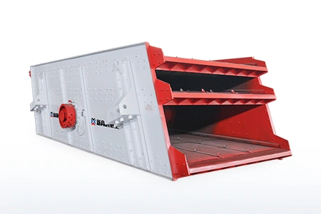
Circular vibrating screens generate an approximately circular or elliptical motion through a single rotating eccentric shaft (exciter). Material moves across the screen deck in a tumbling, stratifying motion that is highly effective for separating coarse, dense particles. The circular vibrating screen mainly screens materials with high specific gravity, large particles, and high hardness. It is widely used in mining industries such as mines, coal, and quarries. The circular motion creates strong agitation of the material bed, which promotes rapid stratification of particles by size and density. The standard inclination angle for circular vibrating screens is typically 15°–20° from horizontal, and the screen is installed at a downward slope so that material travels from the feed end to the discharge end under the combined influence of gravity and vibration.
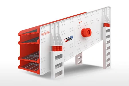
Linear vibrating screens generate a straight-line motion through two counter-rotating exciters (vibration motors) mounted symmetrically on the screen body. The opposing rotation of the two motors produces a resultant force in a single direction, driving material in a straight-line path along the screen deck. Linear screens mainly screen fine particles with light specific gravity and low-hardness, mainly dry materials. They are usually used in food, chemical, building materials, and pharmaceutical industries. Linear screens are installed at a shallower inclination or even horizontally, which increases the residence time of material on the deck and improves separation accuracy for fine particles. Their lower agitation intensity makes them less suitable for stratifying dense, coarse material.
Elliptical vibrating screens produce an elliptical motion that combines features of both circular and linear motion. By adjusting the ratio of the two vibration components, the screen behavior can be tuned between the high-agitation, high-throughput characteristics of circular motion and the fine-separation accuracy of linear motion. Elliptical screens are particularly effective for wet or near-size material where a combination of good stratification and controlled material transport is needed.
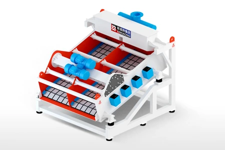
High-frequency vibrating screens operate at much higher frequencies (typically 1,500–3,600 RPM) and low amplitudes (1–3 mm), compared to the lower frequencies (700–1,000 RPM) and higher amplitudes (6–15 mm) of conventional circular or linear screens. High frequency screens allow efficient cuts and fines separations, which can provide high purity and precise sizing control of the product for sizes of fine particles up to 0.074–1.5 mm. They are the equipment of choice for fine iron ore screening, fine coal classification, and dewatering of fine concentrates.
Factor 5: Number of Screen Decks
The number of screen decks — the individual screening surfaces stacked vertically within a single screen body — determines how many product fractions can be produced simultaneously from a single machine.
Single-deck screens produce two product fractions: oversize (material retained on the screen) and undersize (material that passes through). They are used for simple scalping operations, for pre-screening before crushers, and for applications where only two size fractions are required. Single-deck screens have the highest throughput capacity per unit of screen area because the full feed tonnage is presented to a single unobstructed deck.
Double-deck screens produce three product fractions using two screen surfaces with different aperture sizes — a coarser top deck and a finer bottom deck. The oversize from the top deck and the oversize from the bottom deck exit as two separate coarse products, while the combined undersize passes through both decks as the fine fraction. Double-deck configurations are common in aggregate plants producing coarse, medium, and fine fractions simultaneously.

Triple-deck screens produce four product fractions and are widely used in quarries, sand and gravel operations, and mineral processing plants where multiple product sizes must be generated efficiently. The upper deck handles the highest impact load and typically uses the coarsest aperture and heaviest screen media. The lower decks handle progressively finer material and require tighter aperture tolerances.

Beyond three decks — Some manufacturers offer screens with four or five decks, enabling simultaneous production of five or six product fractions from a single machine. Multi-deck configurations often up to 5 decks enable separation of bulk material into 6 to 8 size fractions simultaneously. However, screens with more than three decks require careful attention to feed distribution across all decks and may experience reduced efficiency on lower decks due to restricted air circulation and limited access for screen media inspection and replacement.
Factor 6: Wet or Dry Screening
Whether the screening operation will be conducted dry or with the addition of water is a decision that significantly affects equipment design, screen media selection, and plant layout.
Dry screening is preferred when the material is already at a moisture content below approximately 3–4% and the process does not require washed, clean aggregate. Dry screening is simpler, requires no water handling infrastructure, and produces a dry product that can be stockpiled directly. However, dry screening becomes progressively less effective as moisture content rises. At moisture contents above 8%, fine particles begin to agglomerate and adhere to the screen media, causing blinding that rapidly reduces efficiency and throughput.
Wet screening involves the addition of wash water — either at the feed point, through spray bars above the screen deck, or both — to flush fine particles and clay through the screen apertures. Wet screening is more effective than dry screening for materials with high clay or slime content, for products that require a clean, washed specification, and for fine separation below approximately 5 mm where dry screening efficiency drops significantly. The addition of water typically increases screening capacity by 20–40% compared to dry screening of the same material, because the water acts as a transport medium that helps near-size particles pass through the apertures. The trade-off is the need for water supply, water management, and slurry handling infrastructure.
Dewatering screens are a specialized category designed not primarily for size classification but for solid-liquid separation. They are installed at a slight upward inclination (typically 5°–7° above horizontal) and use high-frequency, low-amplitude vibration to compact and dewater the material bed as it travels up the screen surface. Dewatering screens are commonly used to recover fine sand from classifier overflow, to dewater flotation or gravity concentrates before filtering, and to reduce the moisture content of fine coal or mineral tailings before disposal or further processing.
Key decision rule — If the feed material moisture content exceeds 8%, or if the product must meet a washed specification, or if the separation cut point is below 5 mm, wet screening should be strongly considered over dry screening as the primary operating mode.
Factor 7: Screen Media Selection
Screen media — the actual screening surface through which particles must pass — is the component that most directly determines separation accuracy, throughput, wear life, and operating cost. Selecting the wrong screen media for the material and application is one of the most common causes of chronic screening problems.
Woven wire mesh is the most widely used screen media type across mining, aggregate, and quarry operations. It offers the highest open area (typically 40–65% of total deck area) of any screen media type, which maximizes throughput capacity. Wire mesh is available in carbon steel, stainless steel, high-manganese steel, and various alloy compositions to match different levels of abrasiveness and corrosion. The primary limitation of wire mesh is wear life — in highly abrasive applications such as silica sand, granite, or iron ore screening, wire mesh may require replacement every 4–8 weeks, which imposes significant maintenance labor and consumables costs.
Polyurethane screen panels offer dramatically longer wear life than wire mesh — typically 6 to 8 times longer in abrasive applications — along with significantly lower noise levels (because polyurethane panels dampen vibration rather than amplifying it as metal mesh does) and a natural resistance to blinding in wet applications. The trade-off is lower open area (typically 25–45%) compared to wire mesh, which reduces throughput capacity per unit of screen area. Polyurethane panels are the preferred choice for wet screening, fine particle applications, and any operation where noise reduction or extended media life is a priority.
Rubber screen panels offer the highest resistance to impact from large, heavy particles and are commonly used on the feed end of upper screen decks in quarry and mine applications where large-diameter rocks impact the screen surface on entry. Rubber panels have the lowest open area of the three main media types (typically 20–35%) but provide excellent durability under high-impact conditions and are effective at reducing screen body vibration transmission to the supporting structure.
Perforated steel plate is used for the coarsest applications, where aperture sizes exceed 50–100 mm and the mechanical strength of the screen media must withstand the direct impact of large boulders or run-of-mine ore. Perforated plate has low open area but extremely high structural strength and is essentially immune to wear from impact.
Screen media selection summary:
| Media Type | Open Area | Wear Life | Noise | Best Application |
|---|---|---|---|---|
| Woven Wire Mesh | 40–65% | Short–Medium | High | Dry coarse/medium screening, maximum throughput |
| Polyurethane Panel | 25–45% | Long | Low | Wet screening, fine particles, abrasive materials |
| Rubber Panel | 20–35% | Long | Medium | High-impact feed zones, coarse dry screening |
| Perforated Steel | 15–30% | Very Long | High | Very coarse scalping, heavy-duty primary screening |

Factor 8: Installation Type and Integration with the Plant Circuit
The final selection factor concerns how the screen will be installed within the plant structure and how it will integrate mechanically and operationally with the surrounding equipment.
Mounted (bearing) installation — The majority of industrial vibrating screens are mounted directly on rubber or steel spring isolators that rest on a structural steel or concrete support frame. This configuration is stable, easy to inspect, and allows straightforward access for screen media replacement and maintenance. It is the standard installation method for most mining and aggregate applications.
Suspended (hanging) installation — In some plant configurations, the screen is suspended from above by spring hangers rather than supported from below. When it is necessary to use a suspending vibrating screen, the lifting height should be minimized as much as possible to reduce the swing amplitude of the vibrating screen and facilitate production operations. Suspended screens are sometimes preferred when the supporting structure below the screen must remain unobstructed for material discharge or conveyor routing. However, they require more robust suspension hardware and more careful attention to dynamic loads imposed on the overhead structure.
Integration with upstream crushers and mills — The screen must be positioned and sized to handle the full discharge of the upstream equipment without overloading. Feed distribution across the full width of the screen is critical: a concentrated feed stream entering only one side of the screen deck will cause uneven wear, reduced efficiency, and potential structural overload. A vibrating grizzly feeder or distribution chute is typically used to ensure that feed enters across the full deck width.
Integration with downstream conveyors and processing equipment — The product fractions leaving the screen must fall or flow to downstream conveyors, storage bins, or processing equipment at the correct rate and in the correct location. Screen discharge points, chute angles, and conveyor belt speeds must all be coordinated to prevent material blockages, conveyor overloading, or product cross-contamination between size fractions.
Structural dynamic loads — A vibrating screen transmits significant dynamic forces to its supporting structure through the isolation springs. These forces must be accounted for in the structural design of the supporting frame and the building or plant structure in which the screen is installed. The screen manufacturer should provide dynamic load data — including static weight, dynamic amplitudes, and operating frequencies — for use by the structural engineer during building or platform design.
Common Screen Selection Mistakes to Avoid
Even with the eight factors above properly addressed, several recurring mistakes continue to cause problems in real-world installations:
Ignoring near-size particle content — Near-size particles (those within ±25% of the aperture size) are the most difficult to classify accurately and have a disproportionately large effect on required screen area. A feed containing 30% near-size particles requires significantly more deck area than the same tonnage of material with only 10% near-size — yet this factor is frequently overlooked when screen area is estimated from simple capacity tables.
Underestimating the effect of moisture — Moisture content is often not measured systematically before equipment selection, particularly in projects where feed material samples are taken during dry weather or from dried stockpiles. If the actual operating moisture content is higher than the value used in the screen sizing calculation, the installed screen will consistently underperform.
Selecting screen type based on price alone — The purchase price of a vibrating screen is typically a small fraction of its total cost of ownership over a 10–15 year plant life. A lower-cost screen that requires more frequent media replacement, consumes more power, or operates at lower efficiency will almost always cost more in total than a higher-quality unit selected correctly for the application.
Neglecting feed distribution — A screen cannot perform better than its worst-fed area. If the feed stream is concentrated at one side or one end of the deck, the effective screening area is reduced and local wear is accelerated. Feed distribution systems should be specified and engineered as carefully as the screen itself.
Specifying insufficient safety margin — Screens specified with no throughput safety margin will be at or above their design limit from day one of operation. As the plant ramps up to full production, feed rates typically increase beyond initial design values, and the screen quickly becomes the bottleneck.
Vibrating Screen Sizing Reference Table
The following table provides indicative capacity ranges for common industrial vibrating screen configurations as a starting-point reference. These figures assume standard dry screening conditions with medium-density aggregate (approximately 1.5–1.7 t/m³) and a screening efficiency target of 85–90%. Actual required screen areas should be calculated using VSMA methodology or the specific manufacturer's sizing tools.
| Screen Size | Deck Config. | Approx. Capacity (TPH) | Typical Application |
|---|---|---|---|
| 1.2 m × 3.0 m | Single deck | 40–80 | Small quarry, pilot plant |
| 1.5 m × 4.8 m | Single deck | 80–150 | Medium quarry, aggregate |
| 1.8 m × 4.8 m | Double deck | 120–200 | Aggregate, two-product split |
| 1.8 m × 6.0 m | Double deck | 150–280 | Mining pre-screen, aggregate |
| 2.4 m × 6.0 m | Triple deck | 250–450 | Large quarry, three products |
| 3.0 m × 7.3 m | Triple deck | 400–700 | Large mining, high capacity |
| 3.6 m × 9.7 m | Triple deck | 600–1,000+ | Major mining operations |
Note: Actual capacity depends heavily on material characteristics, moisture, aperture size, and required efficiency. Always confirm with VSMA calculations or manufacturer technical support.
Conclusion
Selecting an industrial vibrating screen is a multi-variable engineering decision that cannot be reliably made from a catalog specification sheet alone. The eight factors covered in this guide — material characteristics, product size requirements, processing capacity, vibration motion type, number of decks, wet versus dry operation, screen media selection, and installation integration — must all be addressed systematically and in combination. Changing any one of them can shift the optimal equipment specification significantly.
The practical starting point for any screen selection is a comprehensive characterization of the feed material: particle size distribution, bulk density, moisture content, clay content, and abrasiveness. From that foundation, the remaining factors can be worked through in sequence, using VSMA capacity calculations or manufacturer-specific sizing tools to confirm that the specified screen will perform within its design envelope under actual operating conditions.
For operations where material characteristics vary significantly between seasons, ore zones, or production campaigns, selecting a screen with some adjustable parameters — such as variable-speed drives, adjustable inclination, or interchangeable screen media frames — provides operational flexibility that can be worth considerably more than its additional capital cost over the life of the installation.