
A spiral classifier is one of the most reliable and widely used pieces of equipment in mineral processing plants worldwide. Despite the growing adoption of hydrocyclones in large-scale operations, the spiral classifier remains the equipment of choice for countless grinding circuits, sand washing operations, and ore desliming applications — and with good reason. Its operating principle is elegant in its simplicity, its mechanical design is robust, and its tolerance for variable feed conditions makes it a practical workhorse in real-world mining environments.
This guide explains in clear technical detail how a spiral classifier works, what its main components are, how the classification process unfolds step by step, and which operating parameters engineers use to control its performance. Whether you are evaluating equipment for a new processing plant or trying to optimize an existing circuit, understanding the fundamentals of spiral classifier operation is an essential starting point.
What Is a Spiral Classifier and What Does It Do?
A spiral classifier is a mechanical device that separates solid particles suspended in a liquid slurry into two distinct fractions based on differences in particle size and specific gravity. The underlying physical principle is differential settling velocity: in a liquid medium, larger and denser particles settle to the bottom more quickly than smaller or lighter ones. The spiral classifier harnesses this difference by providing a controlled settling zone in which fine particles remain in suspension and overflow the tank, while coarse particles sink, are collected at the bottom, and are mechanically conveyed upward for discharge or return to the grinding mill.

In the context of a mineral processing plant, the spiral classifier performs two primary functions:
Classification in closed-circuit grinding — The classifier operates in tandem with a ball mill, intercepting ground ore as it exits the mill and separating it into two streams. Particles fine enough to proceed to the next process stage (flotation, magnetic separation, leaching, etc.) pass over the overflow weir. Particles that are still too coarse are returned to the ball mill for further grinding. This closed-circuit arrangement prevents overgrinding of particles that are already at the correct size, which saves energy and protects downstream process performance.
Ore washing, desliming, and dewatering — In sand washing and gravel processing plants, spiral classifiers remove fine clay, silt, and slime particles from coarser sand and aggregate fractions. The coarse fraction is discharged as a clean, dewatered product, while the fine slurry overflows for further treatment or disposal.
The Core Working Principle: Differential Settling Velocity
The spiral classifier operates on a straightforward physical principle. When solid particles of different sizes and densities are suspended in water and allowed to settle, they do not all fall at the same speed. Stokes' Law and its practical extensions tell us that settling velocity increases with particle size and particle density and decreases with the viscosity of the liquid and the presence of fine slimes.
In a spiral classifier, the ore slurry is introduced into an inclined, U-shaped tank filled with water. The tank is deliberately kept relatively quiet — the spiral rotates slowly and at low speed — so that gravitational settling can proceed without excessive turbulence. In this environment:
Coarse, dense particles experience high settling velocities. They descend through the slurry quickly, reach the bottom of the tank, and accumulate as a bed of sediment. These particles are referred to as the sand return (or underflow).
Fine, light particles have low settling velocities. They remain in suspension within the upper layers of the slurry and are gradually carried by the liquid flow toward the lower end of the tank, where they spill over the overflow weir and exit as the overflow product.
The slowly rotating spiral serves two purposes simultaneously: it gently agitates the slurry to maintain fine particles in suspension and prevent premature settling at the feed end, and it continuously scrapes the settled coarse material from the bottom of the tank and conveys it upward along the inclined trough toward the discharge point at the upper end.
This combination of controlled settling, gentle agitation, and mechanical conveying is what distinguishes the spiral classifier from simpler separation devices such as settling ponds or sluice boxes, and gives it the consistent, controllable performance required in a continuous industrial operation.

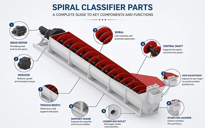
Key Components of a Spiral Classifier
Understanding how a spiral classifier works requires familiarity with its main structural components and what each one contributes to the classification process.
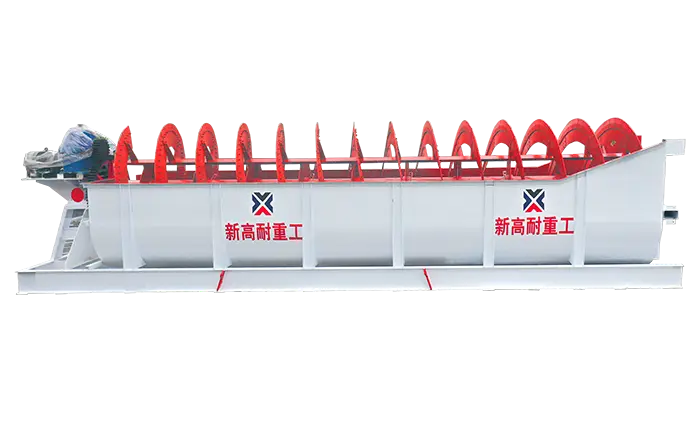
1. Inclined U-Shaped Tank (Trough)
The tank is the main structural body of the spiral classifier. It is fabricated from steel plate and formed into a U-shaped cross-section to match the profile of the rotating spiral blades. The tank is installed at an incline, typically at an angle of 16° to 18° from horizontal, though the exact angle is determined during plant design based on the required classification fineness and the characteristics of the ore being processed.
The lower end of the tank (the overflow end) is where the fine slurry exits over the weir. The upper end is where the coarse sand is discharged. The interior of the tank is fitted with wear-resistant liners along the bottom and sides to protect the steel structure from the abrasive action of the slurry. The trough width — which typically exceeds the spiral diameter by 100 to 200 mm — is a key determinant of the classifier's processing capacity: a wider tank supports higher throughput.
2. Spiral Shaft and Blades
The spiral is the central working element of the classifier. It consists of one or two helical blades (flights) welded to a central steel shaft that runs the full length of the tank. The blades are designed to closely follow the contour of the tank bottom, allowing them to efficiently sweep the settled sand upward while minimizing the clearance gap through which fine particles could escape.
The spiral blades are typically manufactured from high-chromium alloy steel or coated with rubber or polyurethane liners to resist the abrasive wear caused by continuous contact with coarse sand particles. In highly abrasive applications — such as silica sand washing or coarse iron ore classification — the wear life of the spiral blades is an important operational and cost factor, and blade replacement schedules are incorporated into routine maintenance programs.
Spiral classifiers are available in single-spiral and double-spiral configurations. A double-spiral classifier incorporates two parallel helical shafts within the same tank, effectively doubling the sand conveying and discharge capacity without increasing the tank width proportionally. Double-spiral units are preferred for high-throughput applications where the volume of coarse sand return is large.
3. Drive Mechanism (Motor and Gearbox)
The spiral shaft is driven by an electric motor connected through a heavy-duty gearbox that reduces the output speed to the low rotational rates required for classification — typically 1.5 to 10 revolutions per minute (RPM). The precise speed setting is an important operating parameter: faster rotation increases sand conveying capacity but also intensifies agitation, which tends to carry more coarse particles into the overflow and coarsen the classification cutpoint. Slower rotation reduces turbulence and produces a finer overflow but may be insufficient to convey the volume of coarse sand generated by a high-throughput grinding circuit.
Modern spiral classifiers increasingly incorporate variable-speed drive (VSD) systems, which allow plant operators to adjust the spiral speed dynamically in response to changes in feed rate, ore hardness, or required classification fineness — without stopping the machine or making mechanical adjustments.
4. Overflow Weir
The overflow weir is a structural dam at the lower end of the tank that controls the depth of the liquid pool in the settling zone. Fine particles that remain in suspension are carried by the liquid flow over the top of the weir and collected in the overflow launder for transport to the next processing stage.
The height of the overflow weir is one of the most important adjustable parameters in spiral classifier operation. Raising the weir height increases the depth and surface area of the settling zone, giving particles more time to settle and producing a finer overflow product. Lowering the weir height reduces the settling time and produces a coarser overflow. In standard operation, the weir height is set during commissioning and adjusted infrequently thereafter, as frequent changes disrupt the stability of the classification circuit.
For high weir spiral classifiers, the overflow weir height (H) is typically maintained at 1/4 to 3/8 of the spiral diameter (D), corresponding to an overflow particle size range of approximately 0.83 to 0.15 mm. For submerged spiral classifiers, where the entire spiral at the overflow end is submerged below the liquid surface, the effective weir height is equivalent to 3/4 to 1 times the spiral diameter, enabling finer classification at overflow sizes of 0.15 to 0.07 mm.
5. Lifting Mechanism
The lifting mechanism is a critical safety and maintenance feature located at the lower (overflow) end of the classifier. It allows the spiral assembly to be raised out of the tank when the machine needs to be stopped — for example, during a mill shutdown or power interruption. Without a lifting mechanism, the spiral blades would remain submerged in the settling slurry, which quickly consolidates into a dense, difficult-to-restart bed of sediment that can jam the spiral and damage the drive system when the classifier is restarted.
Modern lifting mechanisms are typically hydraulically or electrically actuated and can be activated either manually by the operator or automatically when a power failure is detected. This feature significantly reduces the risk of costly mechanical damage during unplanned shutdowns.
6. Sand Discharge Outlet
The sand discharge outlet is located at the upper end of the inclined tank, where the coarse sand conveyed by the spiral blades reaches the top of the trough and falls into a discharge chute. In a closed-circuit grinding system, this chute directs the coarse sand directly back into the ball mill feed inlet for re-grinding. The geometry and positioning of the discharge chute are designed to minimize spillage and ensure a smooth, consistent feed to the mill.
7. Feed Inlet
The feed inlet is positioned at an intermediate point along the side of the tank — typically approximately one-third to one-half of the tank length from the overflow end, within the settling zone. This positioning allows the incoming slurry to immediately enter the classification region and begin the settling process rather than being deposited at the far end of the tank where it would need to travel the full length before reaching the overflow.

Step-by-Step Classification Process
With the components understood, the complete classification process can be described as a sequential series of events that occur simultaneously and continuously during normal operation.
Step 1 — Feed IntroductionOre slurry from the ball mill discharge — a mixture of ground ore particles, water, and fine slimes — is fed into the spiral classifier through the side feed inlet, entering the tank within the settling zone.
Step 2 — Settling Zone SeparationAs the slurry enters the liquid pool in the settling zone, particles begin to settle under the influence of gravity at rates determined by their size and density. The slow rotation of the spiral provides gentle, low-energy agitation that keeps fine particles in suspension while avoiding the turbulence that would prevent coarse particles from settling. During this phase, the slurry effectively sorts itself: coarse particles descend toward the tank bottom while fine particles remain suspended in the upper layers of the liquid.
Step 3 — Overflow of Fine ParticlesFine particles that remain suspended in the upper portion of the slurry are carried by the gentle liquid flow toward the overflow weir at the lower end of the tank. Once the liquid level reaches the top of the weir, the fine slurry spills over and is collected in the overflow launder. This overflow product — containing correctly sized particles ready for the next processing stage — flows by gravity to the agitation tank, flotation machine, magnetic separator, or leaching system, depending on the process flowsheet.
Step 4 — Conveying of Coarse SandCoarse particles that have settled to the bottom of the tank are continuously engaged by the rotating spiral blades. The blades sweep the settled sand from the bottom of the trough and push it progressively upward along the inclined tank. As the sand travels up the incline, the excess water drains back down into the liquid pool, providing a degree of natural dewatering. By the time the coarse sand reaches the upper end of the tank, its moisture content has been significantly reduced compared to the original slurry.
Step 5 — Sand Discharge and Return to MillAt the upper discharge end, the dewatered coarse sand falls out of the tank through the discharge outlet and into the chute leading back to the ball mill. This is the sand return, and its volume and consistency are critical parameters in maintaining stable closed-circuit grinding performance. A consistent, well-dewatered sand return helps maintain the grinding concentration inside the ball mill at the level required for optimal grinding efficiency.
Step 6 — Continuous CycleThe spiral classifier operates continuously, with feed slurry entering and fine overflow and coarse sand return leaving simultaneously, around the clock. The steady-state operation of a well-tuned closed-circuit grinding system — where the overflow particle size distribution, sand return rate, and mill feed concentration are all within their target ranges — is one of the foundations of efficient mineral processing plant performance.
Key Operating Parameters and Their Effects
Four primary parameters govern the classification performance of a spiral classifier. Plant operators adjust these parameters — within the constraints set by the physical design of the machine — to achieve the desired overflow particle size and sand return properties.
Spiral Rotational Speed
The rotational speed of the spiral, typically measured in revolutions per minute (RPM), controls both the agitation intensity in the settling zone and the rate at which coarse sand is conveyed to the discharge. The practical operating range for most spiral classifiers is 1.5 to 10 RPM.
Increasing the speed raises the sand conveying capacity, which is necessary when the ball mill is producing a large volume of coarse material. However, higher speed also increases turbulence in the settling zone, which tends to carry coarser particles into the overflow, resulting in a coarser-than-desired overflow product. Decreasing the speed reduces turbulence and produces a finer overflow, but risks creating a sand buildup in the tank if the conveying capacity becomes insufficient to handle the incoming coarse material load.
Overflow Weir Height
As described in the components section, the weir height directly controls the depth and area of the settling zone. The height of the overflow weir of a high weir spiral classifier is typically controlled within the range of 400 to 800 mm, while for submerged types the effective weir height is generally between 930 and 2000 mm. Raising the weir increases settling residence time, producing finer overflow; lowering it reduces settling time and coarsens the overflow. In practice, weir height is set at commissioning and adjusted only when a significant and sustained change in required classification fineness is needed.
Feed Slurry Concentration
The concentration of solids in the incoming feed slurry — expressed as a percentage by weight or as a solids-to-liquid ratio — has a strong influence on classification efficiency. At higher concentrations, the increased viscosity of the slurry slows the settling of all particles, meaning that some coarse particles that should report to the sand return instead remain in suspension and appear in the overflow. This increases the coarse particle content of the overflow product, which is generally undesirable.
Conversely, at very low concentrations, the slurry is too dilute to maintain adequate separation between the fine and coarse fractions, and excessive dilution of the overflow can cause problems for downstream processes such as flotation that operate best within a defined pulp density range. The optimal feed concentration must be determined through mineralogical testing and operational experience, and is typically maintained by controlling the water addition rate at the ball mill or at the classifier feed point.
Feed Rate and Uniformity
Maintaining a stable and consistent feed rate to the spiral classifier is essential for achieving consistent classification performance. Fluctuations in feed rate — caused by irregular ore hardness, ball mill operating instability, or upstream feeding problems — lead to corresponding fluctuations in the classification fineness, which propagate downstream as variability in flotation or leaching feed quality. Well-designed grinding circuits incorporate feed rate monitoring and control systems specifically to protect the stability of the classification operation.
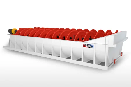
Single Spiral vs. Double Spiral Classifiers
Beyond the type distinction between high weir and submerged configurations, spiral classifiers are also differentiated by the number of spiral shafts installed in the tank.
Single Spiral Classifiers contain one helical shaft and are the standard choice for small- to medium-scale operations where the volume of sand return is manageable with a single conveying mechanism. They are simpler to maintain and have a lower capital cost than double-spiral units.
Double Spiral Classifiers incorporate two parallel helical shafts rotating in the same direction within a single, wider tank. The dual spirals provide approximately twice the sand conveying and discharge capacity of a single unit at the same tank width, making them well suited for high-throughput grinding circuits where large volumes of coarse sand must be returned to the mill. Double-spiral classifiers are common in large-scale gold, copper, and iron ore processing plants where ball mill throughput may reach hundreds of tonnes per hour.

Where Spiral Classifiers Fit in the Mineral Processing Flowsheet
In a typical mineral processing plant, the spiral classifier is positioned immediately downstream of the ball mill and upstream of the primary separation operation (flotation cells, magnetic separators, leaching tanks, or gravity separation equipment). It receives the full discharge of the ball mill, performs the size classification function, recycles the coarse fraction back to the mill, and delivers a correctly sized overflow to the next stage.
The overflow from a spiral classifier is typically directed to an agitation tank for reagent conditioning before flotation, or directly to a thickener or classification cyclone for further size control before leaching or magnetic separation. In some plant configurations, a spiral classifier is also used ahead of a second-stage ball mill in a two-stage grinding circuit, where it performs an intermediate classification between the primary and secondary grinding stages.
In gravity separation and sand washing circuits, the spiral classifier operates somewhat differently — it serves primarily as a washing and desliming unit rather than a grinding circuit classifier, removing fine clay and slime from coarse sand and gravel before the material proceeds to further washing, screening, or stockpiling.
Advantages of the Spiral Classifier in Mineral Processing
The spiral classifier's continued widespread use in mineral processing plants — despite the availability of more technically advanced alternatives — reflects a set of genuine operational advantages:
Mechanical simplicity and reliability. The spiral classifier has very few moving parts. The drive system, the spiral shaft, and the lifting mechanism are the primary mechanical elements, all of which are robust, well-understood, and straightforward to maintain. In remote mining locations where access to skilled maintenance personnel and spare parts can be limited, this simplicity is a significant practical advantage.
Buffer capacity in grinding circuits. The large liquid pool of the spiral classifier acts as a hydraulic buffer that absorbs feed rate fluctuations from the ball mill, damping their effect on the overflow quality. A hydrocyclone, by contrast, responds almost instantaneously to changes in feed pressure and flow rate, which can cause significant instability in the overflow particle size distribution.
Self-regulating sand return. The spiral classifier naturally adjusts its sand return rate in response to changes in the volume of coarse material settling in the tank. When more coarse material is present, more settles and the spiral conveys more sand return; when less is present, less is returned. This self-regulating behavior contributes to grinding circuit stability without requiring active control intervention.
Effective dewatering. The upward conveying action of the spiral provides natural dewatering of the sand return, delivering a relatively low-moisture coarse product back to the ball mill. This helps maintain the grinding concentration inside the mill within its optimal range.
Conclusion
The spiral classifier is a deceptively simple piece of equipment that performs a critical function in mineral processing circuits around the world. Its working principle — differential settling velocity in a controlled liquid environment, combined with mechanical conveying of the coarse fraction — is elegant, reliable, and well suited to the demands of continuous industrial operation. Understanding the role of each component, the mechanics of the classification process, and the effect of key operating parameters is fundamental knowledge for anyone involved in the design, commissioning, or operation of a mineral processing plant.
For those evaluating spiral classifiers for a new installation or seeking to optimize an existing circuit, the key takeaways are clear: match the classifier type (high weir vs. submerged) to the required overflow particle size, size the unit appropriately for the mill's sand return volume, and ensure that feed rate and slurry concentration are kept stable to maximize classification consistency.