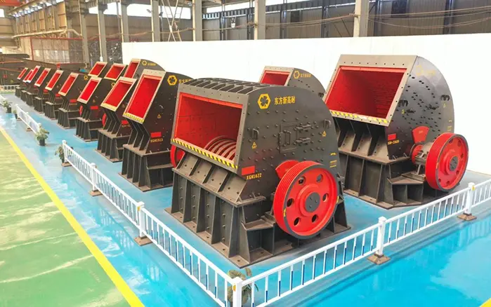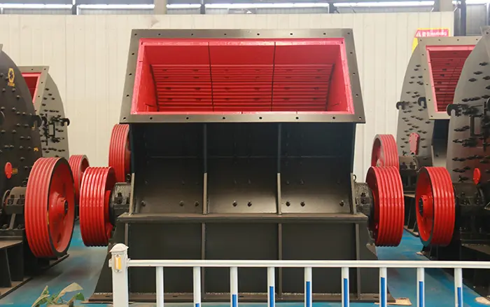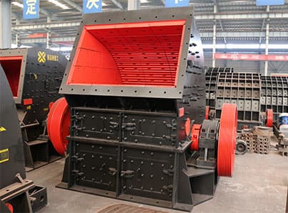
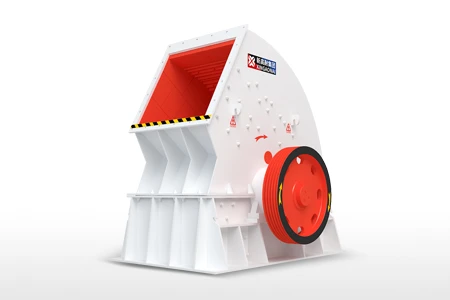
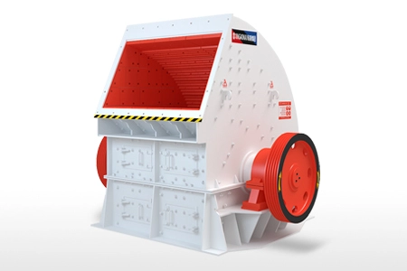
Hammer crusher parts work together to receive material, generate impact energy, control the crushing process and discharge the finished product.
The main components include the feed inlet, crusher housing, rotor, main shaft, rotor discs, hammer heads, hammer pins, liners, bearings, drive system and discharge structure. Each part has a different function, operating load and replacement requirement.
Understanding these components helps operators:
Identify the source of abnormal vibration or noise
Order compatible replacement parts
Plan spare-parts inventory
Reduce maintenance time
Prevent secondary damage
Maintain stable crushing capacity
Component arrangements vary between traditional grate-type machines and modern grate-free designs. Always confirm the actual crusher model and assembly drawing before ordering parts.
For an overview of the crushing process, read what a hammer crusher is and how it works.
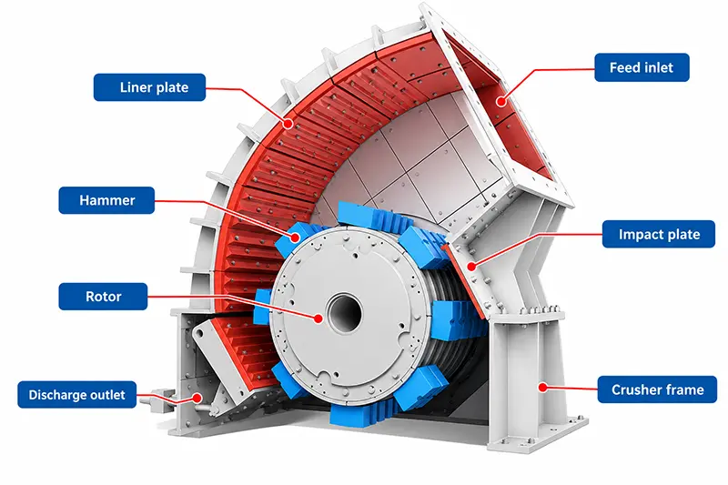
Hammer Crusher Parts at a Glance
| Component | Main function | Common warning signs |
|---|---|---|
| Feed inlet and chute | Guide material into the chamber | Blockage, uneven feeding or material leakage |
| Crusher housing | Support and enclose the crushing chamber | Cracks, loose joints or deformation |
| Rotor assembly | Generate and transmit impact energy | Vibration, imbalance or abnormal noise |
| Main shaft | Support the rotor and transmit torque | Runout, cracks or bearing overheating |
| Rotor discs | Support hammer pins and maintain spacing | Cracks, hole wear or deformation |
| Hammer heads | Strike and break the material | Reduced capacity, coarse product or vibration |
| Hammer pins | Connect hammers to the rotor | Elongation, bending or excessive clearance |
| Liners | Protect the crusher housing | Localized wear or housing exposure |
| Discharge system | Release material at the required size | Blockage or inconsistent product size |
| Bearings | Support the rotating shaft | Heat, noise or excessive vibration |
| Drive system | Transfer motor power to the rotor | Belt slip, misalignment or unstable speed |
| Lubrication system | Reduce friction and protect bearings | Leakage, contamination or overheating |
| Frame and base | Support the machine and absorb loads | Loose bolts, movement or structural cracks |
| Guards and access doors | Protect operators and provide access | Loose guards or damaged interlocks |
1. Feed Inlet, Hopper and Chute
The feed inlet is where raw material enters the crusher. Depending on the production line, material may be delivered by a vibrating feeder, conveyor or loading hopper.
The feed chute directs the material toward the rotor.
Its design should:
Distribute material across the rotor width
Prevent uncontrolled impact on one side
Reduce material leakage
Accommodate the permitted maximum feed size
Protect the housing from direct abrasion
Uneven feeding can cause localized hammer wear, rotor imbalance and unstable motor load.
Feed chutes may include replaceable protective plates in high-wear areas. These plates should not be confused with the internal crushing-chamber liners.
The feed size must match the selected model. The XGN-Z Series heavy hammer crusher is designed for larger feed sizes and higher capacities than the XGN-Q Series.
2. Crusher Housing and Frame
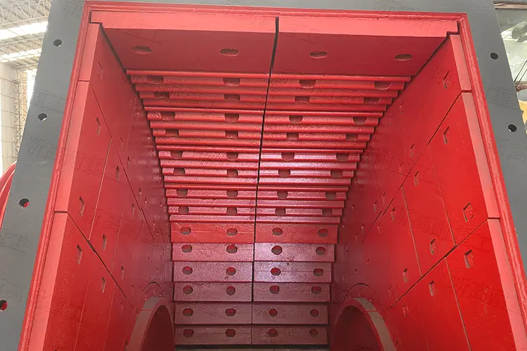
The crusher housing encloses the rotor and crushing chamber. It also supports liners, access doors and other internal components.
The housing normally consists of:
Upper housing
Lower housing
Side plates
Inspection doors
Internal mounting points
Structural reinforcement
Sealing surfaces
The frame and base transfer operating loads to the foundation.
A damaged or incorrectly installed frame may result in:
Machine movement
Loose foundation bolts
Misalignment
Increased vibration
Cracks around welded or bolted joints
Uneven bearing loads
Housing cracks should not be repaired without investigating the underlying cause. Rotor imbalance, foundation problems, loose components or repeated material blockage may cause the damage to return.
3. Rotor Assembly
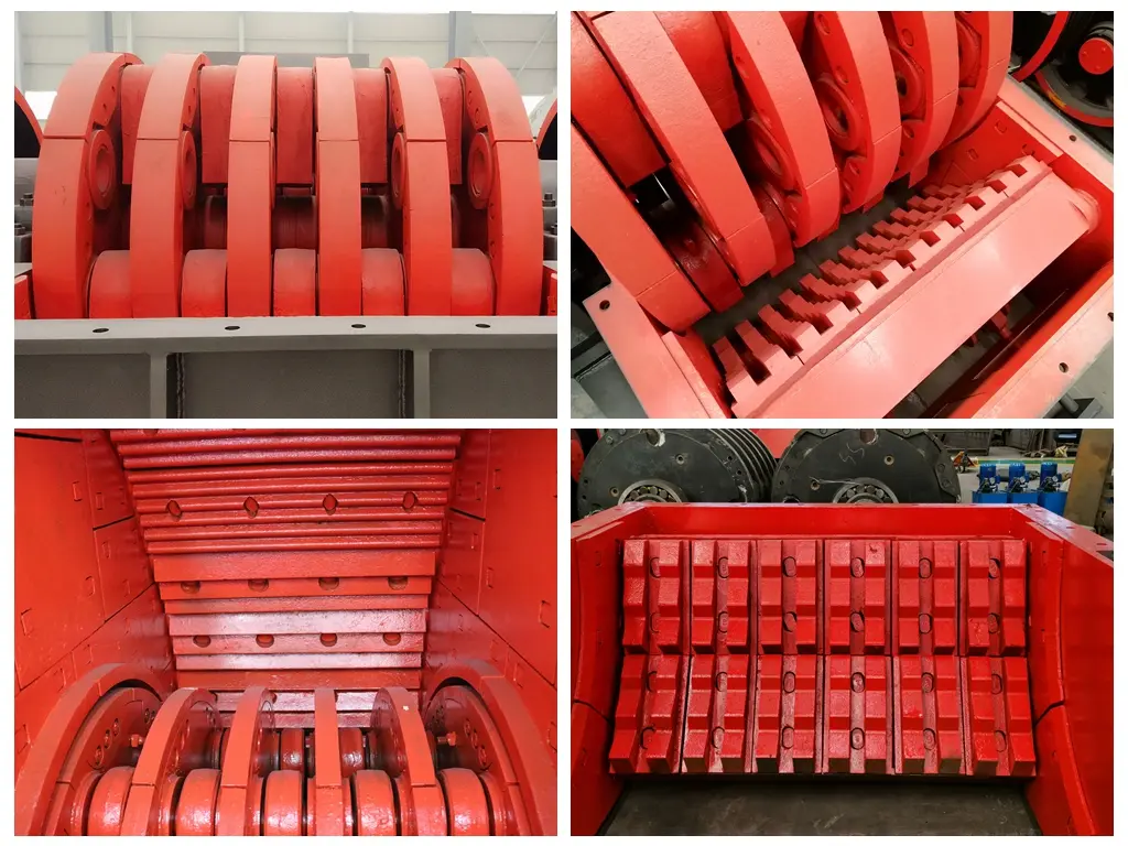
The rotor is the main rotating assembly of a hammer crusher. It converts motor power into impact energy.
A typical rotor assembly includes:
Main shaft
Rotor discs
Spacers
Hammer pins
Hammer heads
Retaining components
Protective plates
Locking devices
The exact arrangement depends on the crusher model.
A heavy-duty rotor must remain correctly aligned and balanced. Small differences in hammer weight or material buildup can generate substantial centrifugal force at operating speed.
Main Shaft
The main shaft supports the rotor discs and transfers torque from the drive system.
It is subjected to:
Rotor weight
Bending loads
Torsional loads
Repeated impact
Bearing forces
Vibration
Warning signs of a shaft problem include:
Repeated bearing failure
Abnormal shaft runout
Increasing vibration
Uneven air gaps
Coupling or pulley misalignment
Cracks near shoulders or keyways
Main-shaft inspection and repair should be performed by qualified personnel. Welding or machining a damaged shaft without an engineering assessment may reduce its reliability.
Rotor Discs
Rotor discs hold the hammer pins and maintain the correct hammer arrangement across the rotor width.
Inspect rotor discs for:
Cracks
Deformed edges
Enlarged pin holes
Loose spacers
Uneven wear
Damage around retaining components
Excessively worn pin holes can prevent the hammers from moving correctly and may cause uneven loading.
Spacers and Sleeves
Spacers maintain the correct distance between rotor discs and hammers.
Missing, incorrectly installed or worn spacers can allow axial movement and change the hammer arrangement.
Rotor Protection Components
Depending on the model, protective plates or retaining rings may be used to shield rotor surfaces from direct abrasion and impact.
These components help prevent damage to the more expensive rotor body.
4. Hammer Heads
Hammer heads directly strike the feed material and are the main crushing components.
They may also be called crusher hammers, but they should not be confused with the blow bars used in impact crushers.
The hammers are mounted on pins between the rotor discs. Depending on the design, they may swing during operation or use a more restricted mounting arrangement.
Hammer performance depends on:
Hammer shape
Hammer weight
Mounting position
Material
Heat treatment
Feed material
Rotor speed
Feed distribution
The hammers must be arranged in the correct sequence. Weight differences between opposite positions can produce rotor imbalance.
This article focuses on the hammer’s structural function. For material grades, wear patterns and replacement criteria, see the complete hammer crusher wear parts guide.
5. Hammer Pins and Retaining Components
Hammer pins connect the hammer heads to the rotor discs.
During operation, the pins experience:
Repeated impact
Shear loading
Surface wear
Bending forces
Movement at contact points
A worn pin may create excessive hammer movement and enlarge the mounting holes in the hammer or rotor disc.
Retaining components prevent the pins from moving out of position. Depending on the design, these may include:
Retaining plates
Locking rings
End caps
Bolts
Locking nuts
Safety pins
When replacing hammer pins, inspect the hammer holes, rotor-disc holes and retaining components at the same time.
Installing a new pin in a severely worn hole may not correct the original problem.
6. Crushing Chamber and Internal Liners
The crushing chamber is the enclosed area in which material is broken by the rotating hammers and internal impact surfaces.
Its shape influences:
Material movement
Number of impacts
Crushing ratio
Fine-powder generation
Discharge efficiency
Product size
Replaceable liners protect the main housing.
Common liner locations include:
Side walls
Front wall
Upper chamber
Feed area
Discharge area
High-impact zones
Liners may be secured with bolts, wedges or other retaining systems.
Loose liners can create metal-impact noise and damage the mounting surfaces. Missing or completely worn liners may expose the crusher housing to direct impact.
Detailed liner material selection belongs to the hammer crusher wear parts topic.
7. Impact and Breaker Surfaces
Some hammer crushers use breaker plates, impact plates or shaped internal surfaces to create additional material collisions.
After being struck by the hammer, particles may collide with these surfaces before returning toward the rotor.
These components can influence:
Crushing efficiency
Product size
Material circulation
Fine-material production
Internal wear distribution
The shape and location of impact surfaces vary by machine design. Parts should therefore be ordered using the model, drawing number and dimensions rather than the general description alone.
8. Discharge Components
The discharge structure determines how crushed material leaves the machine.
Traditional hammer crushers may use:
Grate bars
Screen bars
Grate plates
Adjustable gaps
Other models use:
Open discharge
Grate-free discharge
Adjustable discharge openings
Shaped liners and material-guiding channels
Current XINGAONAI heavy and light hammer crusher models may use a grate-free configuration to reduce blockage and improve material flow.
This means grate bars should not be listed as a standard component for every hammer crusher.
Grate Bars
When fitted, grate bars control the maximum particle size leaving the crushing chamber.
Problems associated with grate bars include:
Blockage
Bending
Cracking
Enlarged gaps
Uneven wear
Loose mounting
Grate-Free Discharge Components
A grate-free machine may use an open discharge arrangement, adjustable components or special chamber geometry.
The relevant parts should be identified from the model-specific assembly drawing.
9. Bearings and Bearing Housings
Bearings support the main shaft and allow the rotor to rotate with controlled friction.
The bearing assembly may include:
Rolling bearings
Bearing housings
Seals
End covers
Locking components
Lubrication passages
Temperature sensors
Bearing problems may be indicated by:
Rising temperature
Abnormal noise
Lubricant leakage
Repeated seal failure
Shaft movement
Increasing vibration
An overheating bearing does not always require more grease. Possible causes include excessive lubrication, incorrect lubricant, contamination, belt tension, misalignment, bearing damage or rotor imbalance.
Bearing identification should be based on the equipment manual or the code marked on the original bearing.
10. Drive System
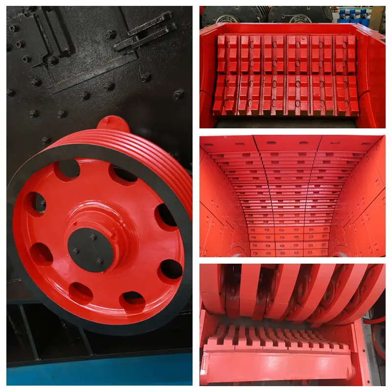
The drive system transfers motor power to the rotor.
Depending on the model, it may include:
Electric motor
Motor base
V-belts
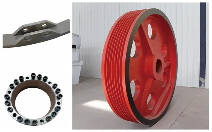
Pulleys
Coupling
Drive guards
Tensioning components
V-Belts and Pulleys
V-belts can absorb part of the shock load while transferring power from the motor to the rotor.
Inspect for:
Cracks
Glazing
Frayed edges
Unequal tension
Belt slip
Pulley wear
Misalignment
Belts installed as a matched set should normally be replaced together.
Couplings
Direct or flexible couplings may be used in some drive arrangements.
Coupling problems can cause vibration, noise and bearing loads. Check alignment after motor, bearing or rotor work.
Motor Base
The motor base provides alignment and belt-tension adjustment.
Loose motor bolts or a deformed base can result in repeated belt problems.
11. Lubrication and Sealing Components
The lubrication system supplies oil or grease to bearings and other specified points.
Components may include:
Grease fittings
Oil lines
Pumps
Filters
Reservoirs
Seals
Breathers
Level indicators
Temperature-monitoring devices
Not every model uses the same lubrication arrangement.
Use the lubricant type, quantity and interval specified for the actual crusher. Avoid applying a universal lubrication interval to every hammer crusher.
Seals help prevent dust and crushed material from reaching the bearings. Damaged seals should be replaced before contamination causes bearing damage.
12. Inspection Doors, Guards and Safety Components
Inspection doors provide access to the crushing chamber for checking hammers, liners, pins and discharge components.
Safety components may include:
Belt guards
Coupling guards
Access-door locks
Interlocks
Emergency-stop devices
Warning labels
Protective covers
The crusher should never operate with guards removed or access doors unsecured.
Before opening the machine, follow the required shutdown and lockout procedure. The complete inspection schedule is available in the heavy-duty hammer crusher maintenance guide.
Wear Parts vs Spare Parts
The terms wear parts and spare parts are related but not identical.
| Category | Definition | Examples |
|---|---|---|
| Wear parts | Components designed to be gradually consumed by impact or abrasion | Hammers, liners, grate bars and rotor protection plates |
| Mechanical spare parts | Components replaced after damage, fatigue or service-life limits | Bearings, shafts, pins, pulleys and couplings |
| Structural parts | Main supporting components that are not normally replaced frequently | Housing, frame, base and major rotor structure |
| Safety parts | Components used to protect personnel and equipment | Guards, interlocks, access-door locks and covers |
A complete spare-parts plan should cover both predictable wear components and critical mechanical parts.
Component Problems and Likely Causes
| Symptom | Components to inspect |
|---|---|
| Excessive vibration | Hammers, rotor, hammer pins, bearings, foundation and drive alignment |
| Bearing overheating | Bearings, seals, lubrication, belts, shaft and rotor balance |
| Coarse finished product | Hammers, impact surfaces and discharge components |
| Low capacity | Feed chute, hammers, chamber, discharge system and belts |
| Metal-contact noise | Liners, hammers, pins, guards and internal fasteners |
| Uneven hammer wear | Feed chute, rotor arrangement and hammer positions |
| Belt slipping | Belts, pulleys, motor base and crusher load |
| Lubricant leakage | Seals, housings, oil lines and grease fittings |
| Repeated pin damage | Hammer holes, rotor-disc holes, pin material and hammer movement |
| Housing cracks | Foundation, rotor balance, loose liners and operating overload |
Symptoms should be investigated as part of the complete machine system. Replacing one damaged part without correcting the cause can result in repeated failure.
How to Identify the Correct Replacement Part
Component names alone are not sufficient when ordering hammer crusher spare parts.
Provide the supplier with:
Crusher manufacturer
Exact model
Machine serial number
Part name
Part number, if available
Assembly drawing
Part dimensions
Material grade
Original part weight
Clear photographs
Required quantity
Description of the failure
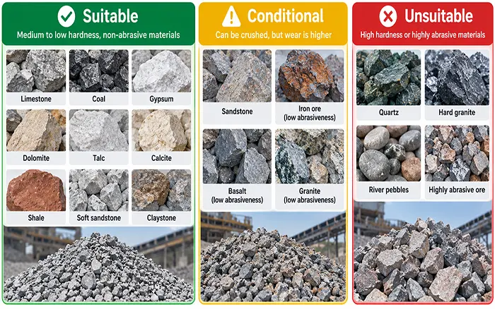
Feed material
Operating conditions
For hammers and other balanced rotor components, provide the required weight tolerance and complete installation quantity.
Do not assume that parts from two crushers with similar capacities are interchangeable. Rotor diameter, shaft size, pin spacing, hole dimensions and mounting arrangements may be different.
Recommended Spare-Parts Inventory
The appropriate inventory depends on operating hours, material abrasiveness and delivery time.
A typical list may include:
Frequently Replaced Parts
Hammer sets
Hammer pins
Retaining components
Liners
Discharge wear components
Drive belts
Critical Mechanical Spares
Bearings
Bearing seals
Coupling elements
Pulley components
Lubrication fittings
Temperature sensors
Safety and Fastening Parts
Liner bolts
Locking nuts
Retaining plates
Access-door seals
Guard fasteners
Inventory should be based on measured consumption rather than guesswork. Record installation dates, running hours and reasons for replacement.
Wear-part consumption can significantly affect the total equipment cost. For budgeting, see the hammer crusher price and operating-cost guide.
How Crusher Model Affects Parts Selection
XINGAONAI offers different hammer crusher series for different feed and capacity requirements.
XGN-Z Heavy Hammer Crusher Parts
The heavy-duty design uses a larger rotor, main shaft, feed opening and structural components to support high-capacity production.
View the heavy hammer crusher model range.
XGN-Q Light Hammer Crusher Parts
The light hammer crusher uses a more compact structure and grate-free discharge arrangement for medium-capacity applications.
View the light hammer crusher model range.
Parts should always be matched to the exact model rather than ordered only as “heavy hammer crusher parts” or “light hammer crusher parts.”
Conclusion
Hammer crusher parts can be divided into crushing components, rotating components, supporting components, drive components, wear parts and safety components.
Correct identification is essential when inspecting the crusher or ordering replacement parts. The model, drawing number, dimensions and material should always be verified before manufacturing or installation.
For large-feed and high-capacity projects, explore the XGN-Z Series heavy hammer crusher.
For smaller feed sizes and medium-capacity applications, explore the XGN-Q Series light hammer crusher.
When selecting equipment or replacement components, a professional hammer crusher supplier should request the machine model, operating conditions and complete part information before providing a recommendation.