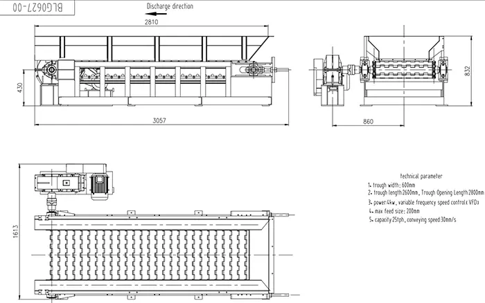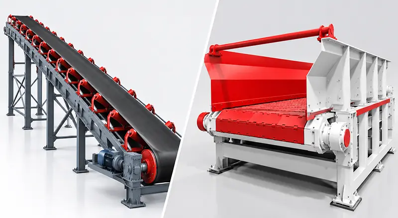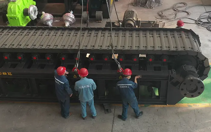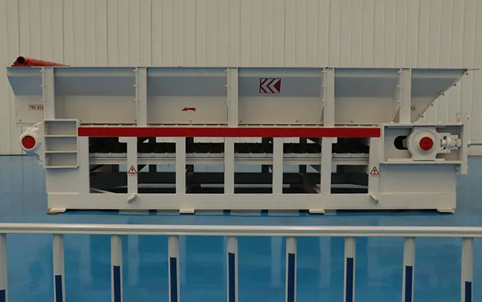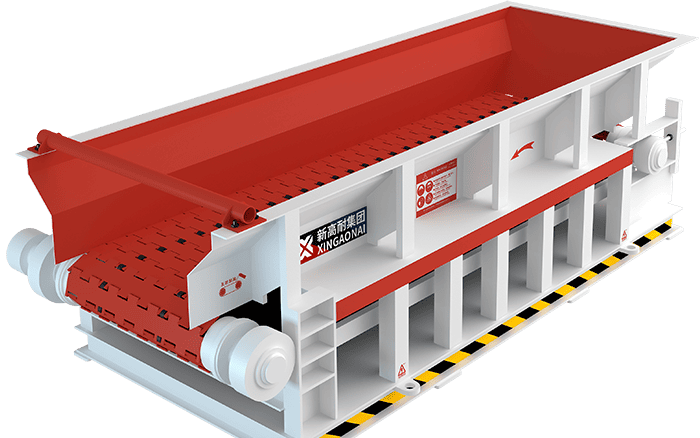
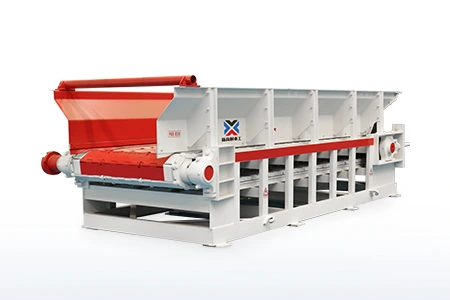
Apron feeders operate under heavy loads, impact, abrasion and continuous material pressure. Their reliability therefore depends not only on the strength of the complete machine but also on the condition and compatibility of individual apron feeder parts.
The main components include apron pans, traction chains, sprockets, shafts, support rollers, the drive assembly, the take-up system, bearings, the main frame and material-retaining structures. Each component has a different function and wear pattern. A problem in one area can quickly affect the rest of the feeder.
For example, worn sprocket teeth can accelerate chain wear, uneven chain elongation can pull the pans out of alignment, and seized support rollers can increase the load on the motor and gearbox.
This guide explains the main parts of an apron feeder, how they work together, common wear signs and what information is required when ordering replacement parts.
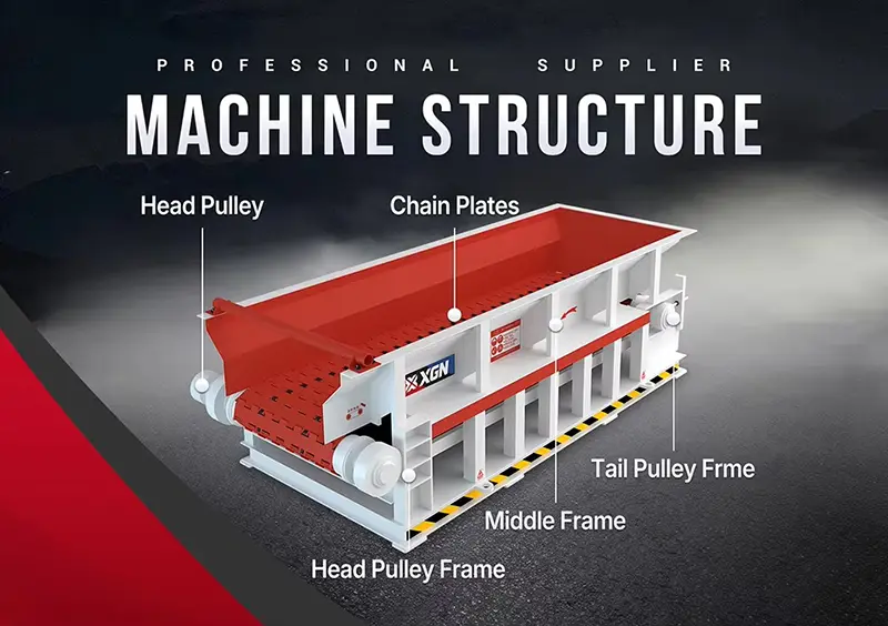
Main Apron Feeder Parts at a Glance
| Component | Main Function | Typical Inspection Focus |
|---|---|---|
| Apron pans | Carry and contain bulk material | Cracks, deformation, wear and loose fasteners |
| Traction chains | Pull the pans and transmit operating load | Elongation, pin and bushing wear, damaged links |
| Drive sprockets | Transfer torque from the drive shaft to the chains | Tooth wear, uneven engagement and alignment |
| Drive shaft | Transfers torque across the feeder width | Bearing condition, alignment and shaft damage |
| Motor and gearbox | Provide and reduce rotational power | Temperature, vibration, oil condition and leakage |
| Couplings | Connect drive components and accommodate limited misalignment | Wear, looseness and damaged flexible elements |
| Support rollers | Support the loaded chain and pan assembly | Seized rollers, uneven wear and bearing damage |
| Return rollers | Support the returning pans and chains | Rotation, alignment and material buildup |
| Take-up system | Maintains the specified chain position and tension | Travel remaining, adjustment and side-to-side balance |
| Main frame | Supports the feeder and material load | Cracks, distortion, loose bolts and corrosion |
| Skirt boards | Keep material on the pans | Liner wear, clearance and material leakage |
| Hopper and chute liners | Protect transfer structures from impact and abrasion | Thickness loss, loose sections and cracking |
| Bearings and seals | Support rotating shafts and retain lubricant | Temperature, noise, leakage and contamination |
| Guards and sensors | Improve operating safety and condition monitoring | Damage, correct positioning and functionality |
1. Apron Pans
Apron pans, also called apron plates or flights, form the moving carrying surface of the feeder. They receive material from the hopper and transport it toward the discharge point.
The pans are normally installed across two parallel traction chains. Their overlapping arrangement helps create a continuous material-carrying surface while allowing the assembly to travel around the drive and tail ends.
Pan geometry must match the feeder design. Important dimensions include:
Overall pan width
Pan depth and profile
Plate thickness
Bolt-hole pattern
Chain attachment spacing
Overlap between adjacent pans
Clearance around the skirt boards
Material and heat-treatment specification
A replacement pan that is approximately the correct width may still be incompatible if its hole pattern, overlap or attachment geometry differs from the original design.
Common Signs of Pan Wear
Inspect apron pans for:
Localized thickness loss
Cracks around bolt holes or reinforced sections
Bent or distorted profiles
Loose, missing or damaged fasteners
Excessive gaps between adjacent pans
Contact with the frame or skirt boards
Material leakage between pans
Uneven wear across the feeder width
A cracked pan should not be considered an isolated cosmetic problem. It may indicate repeated impact, uneven loading, loose mounting hardware, poor chain alignment or insufficient support beneath the loading zone.
2. Traction Chain Assemblies
The chain assemblies pull the pans through the loading, carrying, discharge and return sections of the feeder. They must transmit both the material load and the resistance generated by friction, inclination and material pressure at the hopper outlet.
A chain assembly may include:
Chain links
Pins
Bushings
Rollers or track-contact surfaces
Master or connecting links
Pan attachment points
Retaining hardware
Chain wear is rarely uniform across every link. Contamination, misalignment, impact loading and poor sprocket engagement can create concentrated wear in specific areas.
Important inspection points include:
Increase in chain pitch
Pin and bushing wear
Cracked or distorted links
Loose retaining components
Unequal elongation between the two chain strands
Stiff joints
Side wear
Poor engagement with the sprocket teeth
Chain selection, pitch measurement, lubrication requirements and replacement criteria require more detailed treatment. Refer to the apron feeder chain guide for chain-specific information.
Do not replace an individual link simply because its dimensions appear similar. Chain pitch, link geometry, material, heat treatment and attachment design must all be compatible with the existing assembly.
3. Drive Sprockets
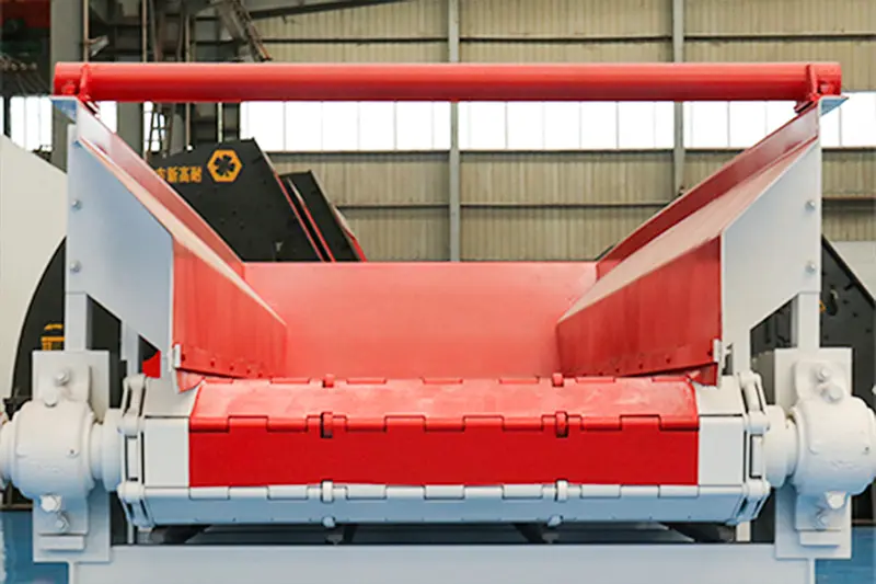
Drive sprockets are mounted on the drive shaft and engage with the chain to move the pan assembly. Their tooth geometry must match the chain pitch and link profile.
Normal contact gradually changes the tooth shape. Abrasive material entering the engagement area can accelerate this process.
Common sprocket problems include:
Hooked or pointed teeth
Uneven tooth thickness
Wear concentrated on one side
Cracked teeth
Loose mounting components
Incorrect alignment between the sprocket and chain
Poor chain seating
Abnormal impact during engagement
If sprocket wear is ignored, a new chain may engage poorly and experience accelerated wear. Chain and sprocket condition should therefore be evaluated together rather than as unrelated parts.
Depending on the feeder design, sprockets may be manufactured as one-piece units or replaceable segments. The correct replacement must match the shaft, mounting arrangement, chain pitch and original tooth profile.
4. Drive Shaft and Bearings
The drive shaft transfers torque from the gearbox to the sprockets across the width of the feeder. It must keep the sprockets correctly positioned relative to both chain strands.
The shaft assembly commonly includes:
Drive shaft
Sprocket hubs or mounting elements
Bearings
Bearing housings
Seals
Retaining components
Keys, locking assemblies or other torque-transfer connections
Possible warning signs include:
Increasing bearing temperature
Abnormal vibration or noise
Lubricant leakage
Shaft movement
Loose bearing-housing bolts
Uneven sprocket alignment
Damaged seals
Contamination inside the bearing housing
Repeated bearing failure may be caused by contamination, incorrect lubrication, misalignment, excessive chain load or structural movement. Replacing the bearing without identifying the underlying cause can result in another premature failure.
5. Motor, Gearbox and Couplings
The drive assembly provides the torque required to start and operate the feeder under load. It normally includes an electric motor, gearbox and one or more couplings. Depending on the equipment configuration, it may also include a variable-frequency drive, torque-limiting device or backstop.
The motor produces rotational power, while the gearbox reduces speed and increases available torque. The coupling connects the drive components and may accommodate limited alignment variation according to its design.
Operators should monitor:
Motor current
Gearbox temperature
Vibration
Abnormal noise
Oil level and condition
Oil leakage
Coupling wear
Loose fasteners
Repeated overload or protective trips
An increase in motor load does not always mean that the motor is undersized. It may be caused by seized rollers, excessive hopper pressure, material buildup, incorrect chain adjustment, damaged bearings or obstruction at the discharge point.
Understanding how an apron feeder works makes it easier to trace a drive problem back through the mechanical system.
6. Support Rollers and Return Rollers
Support rollers carry the weight of the pans, chains and material along the loaded side of the feeder. Return rollers support the unloaded assembly as it travels back toward the tail end.
Roller condition directly affects running resistance and chain tracking. A seized roller forces the chain or pan structure to slide across a stationary surface, increasing friction and localized wear.
Inspect the rollers for:
Free rotation
Flat spots
Damaged surfaces
Bearing noise
Excessive temperature
Seal failure
Material buildup
Loose mounting bolts
Uneven contact
Incorrect alignment
Rollers in the loading zone may experience higher impact loads than those farther along the feeder. The supporting arrangement in this area should therefore be evaluated together with the hopper and impact conditions.
7. Take-Up and Chain Adjustment System
The take-up system positions the tail assembly and compensates for installation tolerances and gradual chain wear. Depending on the feeder design, adjustment may be provided by screw, hydraulic or another mechanical arrangement.
The objective is not to make the chain as tight as possible. Excessive tension can increase loads on the chain, shafts, sprockets and bearings. Insufficient adjustment can allow poor engagement, uncontrolled chain movement or pan misalignment.
Inspection should include:
Remaining take-up travel
Equal adjustment on both sides
Condition of adjustment screws or cylinders
Locking devices
Tail-shaft alignment
Chain position
Signs of abnormal side loading
If one chain strand has elongated more than the other, simply moving one side of the take-up may not correct the actual problem. The chain, sprockets, shaft alignment and pan connections should be inspected as a system.
8. Main Frame and Structural Components
The main frame supports the drive, shafts, chains, rollers, pans and operating material load. It also maintains the alignment required for smooth chain movement.
Structural inspection should look for:
Cracked welds
Distorted members
Loose foundation or structural bolts
Corrosion
Roller-support movement
Misaligned bearing seats
Damage around the loading zone
Contact between moving and stationary parts
Recurring chain-tracking or roller problems may originate from frame distortion rather than the replacement parts themselves.
The frame and support structure must also suit the hopper arrangement, installation angle, feeder length and operating load. These factors should be considered during initial equipment selection, as explained in the apron feeder design and sizing guide.
9. Skirt Boards, Hopper Interfaces and Wear Liners
Skirt boards control material along the sides of the feeder and help prevent spillage. The hopper interface determines how material reaches the pans and how much pressure is applied to the moving bed.
These parts may include:
Skirt plates
Replaceable skirt liners
Hopper liners
Chute liners
Impact plates
Sealing elements
Mounting bars and fasteners
If the skirt clearance is too large, material can escape. If it is too small or the liners are distorted, they may rub against the pans and increase drive load.
Liners should be selected according to the actual material and wear mechanism. High impact, sliding abrasion, moisture and corrosion do not necessarily require the same liner material.
Visible liner wear should be assessed before the supporting structure becomes exposed. Replacement criteria should be based on remaining thickness, attachment condition and risk to adjacent components rather than on a universal operating-hour interval.
10. Guards, Sensors and Lubrication Components
Guards isolate moving components such as chains, sprockets, couplings and drive shafts. They must remain correctly installed during normal operation.
Depending on the feeder configuration, monitoring and safety components may include:
Zero-speed switches
Rotation sensors
Chain-motion sensors
Motor-current monitoring
Bearing-temperature sensors
Pull-cord switches
Emergency-stop devices
Centralized lubrication components
Not every apron feeder uses the same sensor or lubrication arrangement. Lubrication requirements differ between chain designs, bearings, gearboxes and operating environments. Always follow the lubrication specification supplied for the actual machine and component.
Never remove a guard, inspect a moving chain at close range or perform an adjustment while the equipment is energized. Follow the site’s isolation and lockout procedures before maintenance.
Which Apron Feeder Parts Are Wear Parts?
Some components are expected to wear during operation, while others should normally be replaced only after damage, loss of accuracy or the end of their serviceable condition.
| Part Category | Examples | Main Reasons for Replacement |
|---|---|---|
| Material-contact wear parts | Pans, skirt liners, hopper liners and chute liners | Abrasion, impact, deformation and thickness loss |
| Power-transmission wear parts | Chains, pins, bushings, sprockets and coupling elements | Elongation, fatigue, poor engagement and surface wear |
| Rolling components | Support rollers, return rollers and bearings | Seal failure, contamination, fatigue and seizure |
| Sealing and lubrication parts | Seals, gaskets, hoses and lubrication fittings | Leakage, contamination or physical damage |
| Structural parts | Frame sections, shafts and supports | Cracking, bending, corrosion or loss of alignment |
| Monitoring and safety parts | Sensors, switches and guards | Damage, unreliable operation or loss of protection |
A part should not be replaced based only on its age. Condition, measured wear, operating trend and risk to connected components provide a more useful basis for maintenance decisions.
Common Symptoms and Their Possible Causes
| Operating Symptom | Parts to Inspect |
|---|---|
| Pans move toward one side | Chains, sprockets, take-up, shafts, rollers and frame alignment |
| Metallic impact or knocking | Loose pans, damaged links, worn sprockets, loose fasteners or foreign material |
| Increasing motor current | Rollers, bearings, skirt clearance, chain condition and hopper loading |
| Material leakage between pans | Pan deformation, excessive gaps, damaged overlaps or loose connections |
| Uneven chain movement | Chain elongation, stiff joints, sprocket wear or misalignment |
| High bearing temperature | Lubrication, contamination, alignment, seals and applied load |
| Repeated loose pan bolts | Pan distortion, impact loading, mounting-face damage or incorrect fasteners |
| Abnormal gearbox noise | Lubricant condition, gears, bearings, coupling alignment or overload |
| Rapid wear on one side | Uneven loading, structural misalignment, chain mismatch or side contact |
| Poor discharge flow | Material buildup, downstream restriction or unsuitable operating speed |
This table is a starting point rather than a final diagnosis. Several components may contribute to the same symptom.
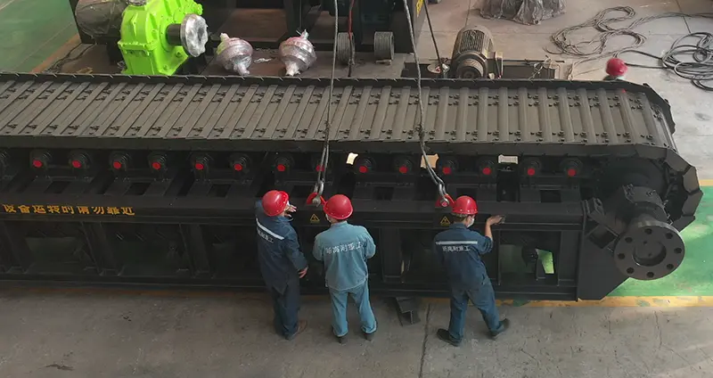
How to Inspect Apron Feeder Parts
A useful inspection program combines visual checks, operating observations and measurements taken during planned shutdowns.
Before Operation
Check for:
Loose or missing fasteners
Visible pan or guard damage
Material buildup
Leakage around the gearbox and bearings
Obstructions near the chain path
Damaged cables, sensors or lubrication lines
During Operation
From an approved safe observation point, monitor:
Unusual noise
Irregular chain movement
Pan tracking
Material spillage
Motor load
Gearbox and bearing condition
Excessive vibration
Changes in feed consistency
During a Planned Shutdown
After the machine has been safely isolated, inspect:
Pan thickness and cracks
Chain pitch over several links
Pin and bushing condition
Sprocket tooth profile
Roller rotation
Bearing play
Shaft alignment
Take-up position
Frame and weld condition
Liner thickness
Fastener condition
Measurements should be recorded consistently. Trend data can identify gradual deterioration that may not be obvious from a single inspection.
How to Select Replacement Apron Feeder Parts
Dimensional compatibility should be confirmed before selecting material upgrades or changing component design.
1. Confirm the Feeder Identity
Provide:
Manufacturer
Feeder model
Serial number
Manufacturing date, if available
Original part number
General arrangement drawing
Parts drawing or manual reference
2. Confirm the Component Dimensions
Depending on the part, required dimensions may include:
Pan width and profile
Plate thickness
Bolt-hole spacing
Chain pitch
Link width
Pin and bushing dimensions
Sprocket tooth count
Shaft diameter
Bearing designation
Roller diameter and face width
Mounting dimensions
3. Describe the Operating Conditions
The supplier should understand:
Material type
Maximum feed size
Bulk density
Moisture content
Abrasiveness
Operating capacity
Loading method
Hopper configuration
Operating hours
Reason for the previous failure
This information helps determine whether the original specification remains suitable or whether the application should be reviewed.
4. Confirm Material and Heat Treatment
Two components with the same visible dimensions may perform differently if their base material, heat treatment, surface hardness or manufacturing accuracy differs.
Harder is not always better. A material that resists abrasion may have insufficient toughness for severe impact. The part specification should match the actual wear mechanism.
5. Check Compatibility with Connected Parts
Before installing a replacement component, inspect the parts that engage with it.
Examples include:
Chain and sprocket
Pan and chain attachment
Shaft and bearing
Roller and support bracket
Coupling and shaft
Liner and mounting surface
Installing a new component against a severely worn mating part can shorten its service life.
Information to Send When Requesting a Spare-Parts Quote
To reduce identification errors, send the following information with the inquiry:
Feeder model and serial number
Part name and original part number
Required quantity
Clear photographs
Photographs of the nameplate
Component drawing, if available
Key dimensions
Material being handled
Description of damage or wear
Required delivery date
Installation location and operating conditions
For chains, pans and sprockets, include photos showing how the parts connect rather than only an isolated view of the worn surface.
Recommended Apron Feeder Spare Parts
The correct spare-parts inventory depends on failure risk, lead time, site location and the number of identical feeders in operation.
A practical inventory may include:
Selected apron pans
Pan mounting hardware
Chain connecting components specified for the feeder
Sprocket segments, where applicable
Support rollers
Return rollers
Bearings and seals
Coupling wear elements
Lubrication fittings and hoses
Sensors and switches
Critical gearbox seals or manufacturer-recommended service parts
Large capital components should be stocked only after evaluating lead time and operational consequences. A documented parts list is more effective than purchasing unrelated components after a breakdown.
How to Reduce Apron Feeder Parts Wear
Control Loading Impact
Material should enter the feeder in the intended loading area. Excessive free-fall height or repeated direct impact on an unsupported pan can damage pans, fasteners and supporting components.
Avoid Uncontrolled Overloading
Operating beyond the designed material bed depth or capacity increases chain pull and loads on the motor, gearbox, shafts and bearings.
Maintain Correct Alignment
Chain strands, sprockets, shafts, rollers and frame supports must remain aligned. Misalignment can create rapid wear on one side of the feeder.
Keep the Return Path Clear
Material buildup around return rollers, chains or pans can increase resistance and force components away from their intended path.
Investigate Repeated Failures
If the same part fails repeatedly, review the complete system. The root cause may be hopper pressure, impact, alignment, material buildup, unsuitable operating speed or a damaged mating component.
Match the Feeder to the Application
Some applications can be handled by lighter feeding equipment, while large, sharp, abrasive or impact-loaded material may require an apron feeder. The belt feeder vs apron feeder comparison explains the main selection differences.
XINGAONAI Apron Feeder Parts Support
XINGAONAI’s BLG Series apron feeder is designed for feeding and short-distance transportation in mining, aggregate, building-material and mineral-processing applications.
The currently published range includes capacities from 200 to 800 t/h and a maximum feed size of up to 500 mm. Actual equipment selection must also consider material properties, hopper conditions, pan width, feeder speed and downstream requirements.
For a new project, supplier evaluation should cover more than the purchase price. Engineering capability, manufacturing control, documentation, testing and spare-parts support all affect lifecycle reliability. See the apron feeder manufacturer selection guide for additional guidance.
When requesting replacement parts, provide the feeder model, serial number, photographs and key dimensions so that compatibility can be checked before production.
Conclusion
Apron feeder reliability depends on the interaction of its pans, chains, sprockets, shafts, rollers, drive system, take-up system and supporting structure.
Replacing the visibly damaged part may restore operation temporarily, but repeated failures usually require a system-level inspection. Chain alignment, sprocket condition, roller rotation, hopper loading and frame accuracy should all be considered before new parts are installed.
For replacement-part identification or a new feeding application, provide XINGAONAI with the feeder model, serial number, photographs, component dimensions and material information. This helps confirm compatibility and reduces the risk of ordering incorrect apron feeder parts.