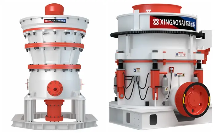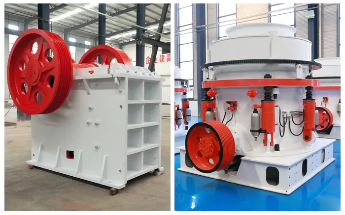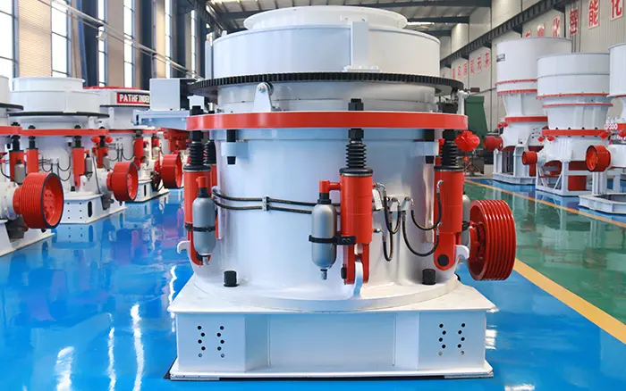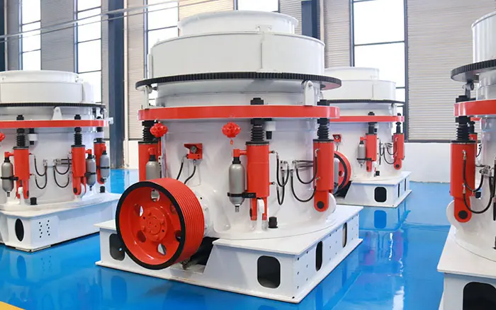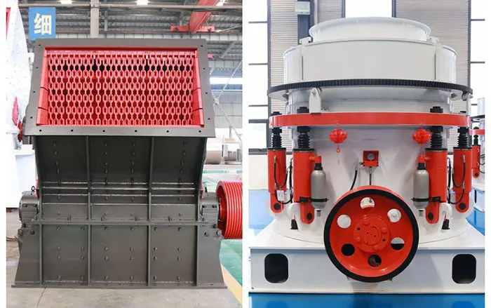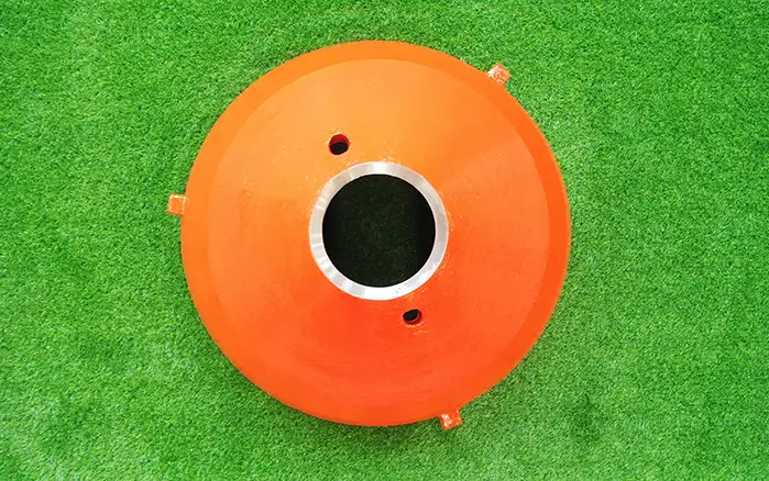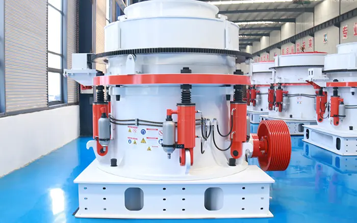
A cone crusher is a machine used to crush rocks and ores in mining and aggregate industries. It works by compressing material between a moving cone (mantle) and a fixed cone (concave). To understand how it works, you need to see its internal parts. This article explains the cone crusher diagram step by step. You will learn the names and functions of each major component, how they fit together, and how the machine operates.
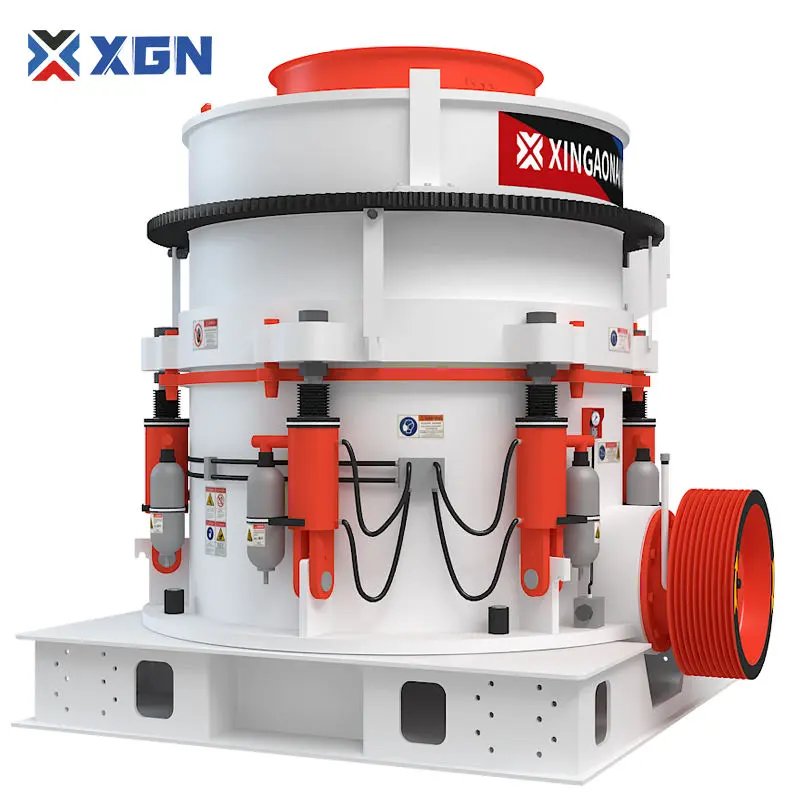
What Is a Cone Crusher?
A cone crusher is a secondary or tertiary crushing machine. It receives material from a primary jaw or impact crusher and reduces it to a smaller, more uniform size. The crushing action happens inside a chamber formed by two cone-shaped liners. The outer liner is called the concave (or bowl liner). The inner liner is called the mantle. The mantle gyrates (moves in a circle) eccentrically inside the concave, crushing the material.
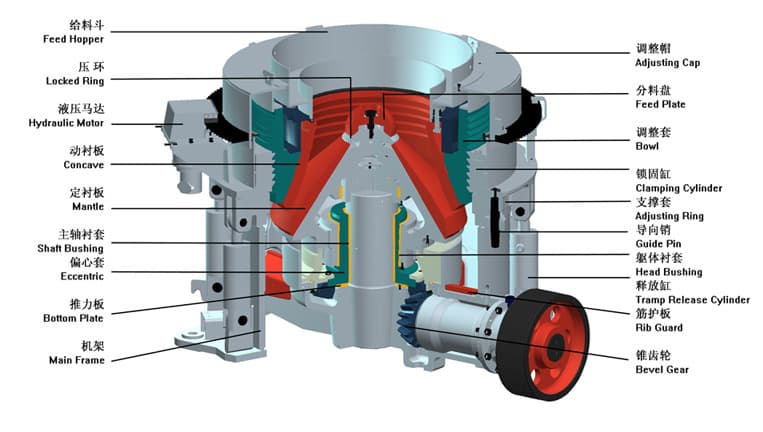
Cone Crusher Diagram: Main Components
Below is a description of the main parts you would see in a typical cone crusher diagram. Imagine a cross‑section view.
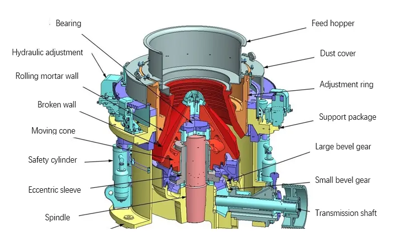
1. Feed Hopper
At the top of the diagram, you see the feed hopper. This is where material enters the crusher. The hopper directs the material down into the crushing chamber.
2. Feed Distribution Plate
Just below the hopper, a distribution plate spreads the material evenly around the crushing chamber. Even feeding prevents uneven wear and improves crushing efficiency.
3. Mantle (Moving Crushing Cone)
The mantle is the inner cone that moves. It is mounted on the main shaft. The mantle’s outer surface is covered with wear-resistant manganese steel. In the diagram, it is shown as the central cone that gyrates.
4. Concave (Bowl Liner)
The concave is the fixed outer liner. It sits inside the crusher bowl. Like the mantle, it is made of manganese steel. The space between the mantle and concave is the crushing chamber. The concave has a ring of crushing teeth or a smooth surface.
5. Crushing Chamber
This is the space where material is crushed. In the diagram, you see the wedge-shaped gap between the mantle and concave. At the top, the gap is wider to accept feed. At the bottom, the gap is narrower to produce a smaller product size.
6. Main Shaft
The main shaft is a vertical shaft that holds the mantle. It is driven eccentrically by the eccentric bushing. The shaft does not rotate on its own; it gyrates.
7. Eccentric Bushing
Located below the main shaft, the eccentric bushing is a steel ring with an offset hole. When it rotates, it forces the main shaft to gyrate. This creates the crushing motion.
8. Countershaft Assembly
The countershaft transmits power from the motor to the eccentric bushing. It consists of a horizontal shaft, pinion gear, and bearings. In the diagram, it is shown on the side of the crusher.
9. Pinion Gear and Eccentric Gear
The pinion gear on the countershaft meshes with a large gear on the eccentric bushing. This rotates the eccentric bushing at a controlled speed.
10. Hydraulic Adjustment System
Many cone crushers have a hydraulic system to adjust the crusher setting (closed side setting – CSS). It allows operators to change the gap between mantle and concave. In the diagram, you see hydraulic cylinders under the bowl or around the main frame.
11. Tramp Release System
If an uncrushable object (like a metal bolt) enters the chamber, the tramp release system allows the concave to lift up. This protects the crusher from damage. After the object passes, the concave returns to its position.
12. Support Bowl and Adjustment Ring
The concave sits inside the support bowl. The adjustment ring sits above the bowl. By turning the adjustment ring, you can raise or lower the concave to change the CSS. The diagram shows these as large threaded rings.
13. Main Frame
The main frame holds all components. It is a heavy steel casting. The eccentric bushing, countershaft, and hydraulic cylinders are mounted on or inside the frame.
14. Dust Seal
A dust seal prevents fine particles from entering the bearings and hydraulic system. It is located between the lower frame and the moving parts.
How the Cone Crusher Works (With Diagram in Mind)
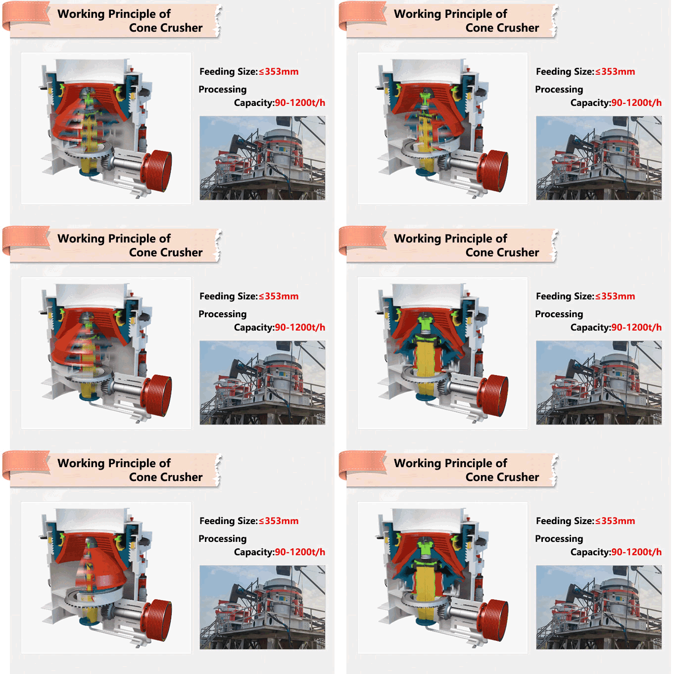
Now that you know the parts from the cone crusher diagram, here is the working sequence:
Material enters the feed hopper and falls onto the distribution plate.
The plate spreads the material evenly into the crushing chamber.
The eccentric bushing rotates, causing the main shaft and mantle to gyrate.
The mantle moves closer to the concave on one side and farther away on the opposite side.
As the mantle approaches the concave, it crushes the material.
Crushed material falls down by gravity to the bottom where the gap is narrowest.
When the mantle moves away, the material drops further.
The process repeats many times until the particles are small enough to exit through the bottom opening.
The hydraulic system maintains the desired CSS. If an uncrushable object enters, the tramp release lifts the bowl, the object passes, and the bowl returns.
Types of Cone Crushers and Their Diagrams
While the basic cone crusher diagram is similar, there are different types:
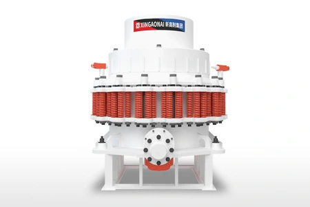
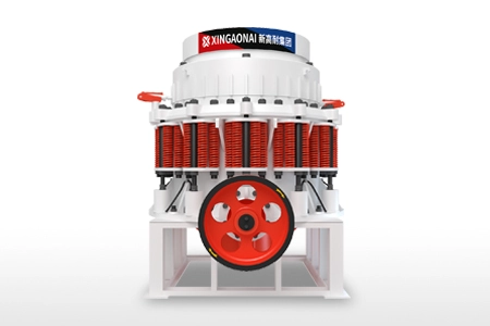
Spring Cone Crusher: Uses springs as tramp release. No hydraulics.
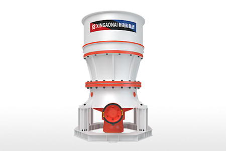
Single-Cylinder Hydraulic Cone Crusher: One hydraulic cylinder at the bottom. Simple and compact.
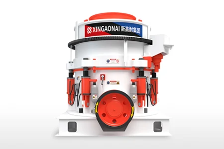
Multi-Cylinder Hydraulic Cone Crusher: Several cylinders around the frame. More precise adjustment and higher performance.
Symons Cone Crusher (Compound): Older design with spring release. Still widely used.
Each type has minor differences in the diagram, but the main components (mantle, concave, eccentric, shaft) are the same.
Why Understanding the Cone Crusher Diagram Helps
Knowing the cone crusher diagram helps operators and maintenance staff:
Identify parts quickly when reading manuals or ordering spares.
Understand where wear occurs (mantle, concave).
Troubleshoot problems: e.g., uneven wear indicates poor feed distribution.
Perform maintenance: e.g., replacing liners, checking eccentric bushing wear.
Adjust CSS correctly using hydraulic or threaded adjustment.
Common Parts Names in a Cone Crusher Diagram
Here is a quick reference list of terms used in typical diagrams:
| Part Name | Function |
|---|---|
| Feed hopper | Receives material |
| Distribution plate | Spreads feed evenly |
| Mantle | Moving crushing cone |
| Concave | Fixed bowl liner |
| Crushing chamber | Gap between mantle and concave |
| Main shaft | Holds mantle, gyrates |
| Eccentric bushing | Creates gyratory motion |
| Countershaft | Transmits power |
| Pinion gear | Drives eccentric gear |
| Adjustment ring | Changes CSS (threaded) |
| Support bowl | Holds concave |
| Hydraulic cylinder | Lifts bowl for CSS or tramp release |
| Tramp release system | Allows uncrushables to pass |
| Dust seal | Keeps out contaminants |
| Main frame | Base structure |
Conclusion
A cone crusher diagram clearly shows the internal layout of this important crushing machine. The key components are the mantle (moving cone), concave (fixed liner), eccentric bushing (makes the mantle gyrate), and the hydraulic system (adjusts setting and provides tramp release). Understanding the diagram helps you operate, maintain, and troubleshoot your cone crusher more effectively. Whether you have a spring, single-cylinder, or multi-cylinder crusher, the basic parts remain the same.