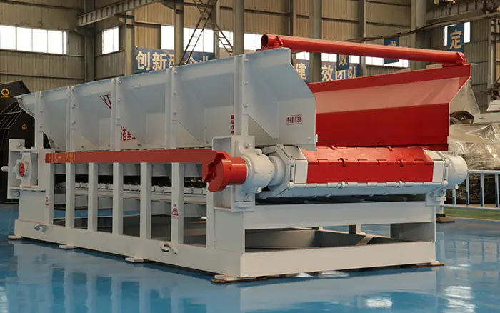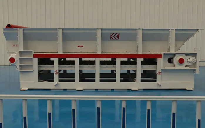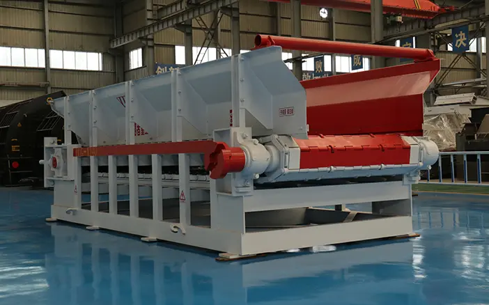
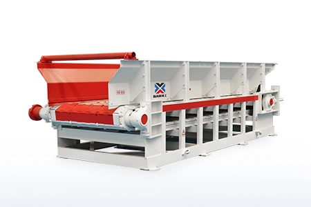
Correct apron feeder design begins with the material and operating conditions—not with a catalogue model number.
Required capacity, maximum lump size, bulk density, moisture content, hopper geometry, material drop height and installation angle all affect the feeder width, bed depth, operating speed, length and drive requirements. Ignoring any of these factors can result in insufficient capacity, material bridging, excessive component wear or failure to start beneath a loaded hopper.
A preliminary capacity calculation can estimate the required material cross-section and feeder speed. However, final apron feeder sizing must also consider hopper pressure, shear resistance, inclination, impact loading, moving component weight and full-load starting torque.
This guide explains the main design steps and the information a manufacturer needs before selecting an apron feeder.
Important: The formulas and examples in this guide are intended for preliminary equipment selection. Final dimensions, structural loads, motor power and gearbox torque should be verified for the actual project.
[Image 1 – Place here]
Suggested image: Side-view diagram showing a hopper, material bed, apron feeder, drive system and downstream crusher.
Alt text: apron feeder design beneath a material storage hopper
Apron Feeder Design Process
A practical apron feeder sizing process normally includes the following steps:
Confirm normal and peak feed rates.
Determine minimum and maximum bulk density.
Identify the maximum lump size and particle-size distribution.
Estimate the required effective material width.
Select a suitable bed depth and operating speed.
Check the hopper opening, shear length and material pressure.
Determine the required feeder length and inclination.
Calculate running resistance and full-load starting torque.
Select the motor, gearbox, chains, pans and support structure.
Verify the design under both normal and abnormal operating conditions.
These parameters are connected. Increasing the feeder speed may reduce the required material cross-section, but it can also increase wear, impact and spillage. Increasing feeder width can improve material flow and reduce speed, but it also increases machine weight and investment cost.
The objective is not to maximize one design parameter. It is to create a balanced system that provides the required feed rate without introducing unnecessary wear, power consumption or material-flow problems.
What Information Is Required for Apron Feeder Design?
The manufacturer should receive complete material, process and installation information before recommending a model.
| Required information | Why it matters |
|---|---|
| Normal feed rate | Establishes the usual operating point |
| Peak or design feed rate | Determines maximum required capacity |
| Minimum bulk density | Used to determine the speed needed to reach the target tonnage |
| Maximum bulk density | Used to evaluate material load and drive torque |
| Maximum lump size | Influences minimum effective feeder width |
| Particle-size distribution | Shows whether maximum-size lumps are occasional or frequent |
| Moisture and clay content | Affects adhesion, flowability and hopper resistance |
| Material abrasiveness | Influences pan, liner and chain selection |
| Hopper opening dimensions | Affect bed formation and shear resistance |
| Material drop height | Determines impact loading on the pans and rollers |
| Feeder length | Influences total material load and running resistance |
| Installation angle | Adds lifting resistance and may affect capacity |
| Downstream equipment | Determines the required feed-control range |
| Site voltage and frequency | Required for motor and electrical selection |
| Ambient conditions | Affect material selection, lubrication and electrical components |
Bulk density is not solid density
One of the most common apron feeder sizing errors is using the solid density of the rock instead of its bulk density.
Solid density represents the density of an individual mineral or rock. Bulk density includes the spaces between particles and represents the mass of material occupying a given volume on the feeder.
Because an apron feeder transports a volume of loose material, bulk density must be used in the capacity calculation.
For materials with variable conditions, the designer should obtain:
Minimum expected bulk density
Maximum expected bulk density
Normal operating bulk density
Density changes caused by moisture
Density changes caused by particle-size distribution
Minimum bulk density is important when calculating the speed required to deliver the specified tonnes per hour. Maximum bulk density is important when calculating material load, chain pull and drive torque.
How Is Apron Feeder Capacity Calculated?
The preliminary capacity of an apron feeder can be estimated from the effective material width, average bed depth, feeder speed, bulk density and filling factor.
The basic formula is:
Q = 3,600 × B × D × V × ρ × F
Where:
Q = Feeder capacity (t/h)
B = Effective material width (m)
D = Average material bed depth (m)
V = Feeder speed (m/s)
ρ = Material bulk density (t/m³)
F = Filling factor
3,600 = Conversion factor from seconds to hours
When the required capacity is known, the feeder speed can be calculated as follows:
V = Q ÷ (3,600 × B × D × ρ × F)
This formula provides an initial capacity estimate. It does not determine:
Hopper discharge behavior
Material bridging risk
Pan impact loading
Required chain pull
Starting torque
Gearbox service factor
Final motor power
Structural support loads
These factors require separate engineering checks.
[Image 2 – Place here]
Suggested image: Cross-section showing effective width, material bed depth and travel direction.
Alt text: apron feeder capacity calculation using width bed depth and speed
Apron Feeder Capacity Calculation Example
Assume the following preliminary design conditions:
Required capacity (Q) = 400 t/h
Effective material width (B) = 1.20 m
Average bed depth (D) = 0.50 m
Minimum bulk density (ρ) = 1.40 t/m³
Filling factor (F) = 0.80
Insert these values into the speed formula:
V = Q ÷ (3,600 × B × D × ρ × F)
V = 400 ÷ (3,600 × 1.20 × 0.50 × 1.40 × 0.80)
First calculate the denominator:
3,600 × 1.20 × 0.50 × 1.40 × 0.80 = 2,419.2
The required feeder speed is therefore:
V = 400 ÷ 2,419.2
V ≈ 0.165 m/s
Convert metres per second to metres per minute:
Feeder speed = 0.165 × 60
Feeder speed ≈ 9.9 m/min
Therefore, the selected material cross-section must travel at approximately 0.165 m/s, or 9.9 m/min, to deliver 400 t/h when the bulk density is 1.40 t/m³.
This is only a preliminary capacity calculation. Before accepting the result, the engineer must verify:
Whether the effective width is sufficient for the maximum lump size
Whether the proposed bed depth is stable
Whether the hopper can discharge uniformly
Whether the speed is suitable for the chain and pan system
Whether the drive can start beneath a loaded hopper
Whether the supporting structure can withstand the load
Whether the calculated speed remains practical across the full density range
The effective material width is not necessarily equal to the overall pan width. Space occupied by skirt liners, side clearances and structural components must also be considered.
How to Select Apron Feeder Width
Apron feeder width must satisfy both capacity and lump-size requirements.
A width calculated only from target capacity may be too narrow for large or irregular rocks. When several large particles arrive at the hopper outlet together, they may form a bridge or become trapped between the skirt liners.
Width selection should consider:
Maximum lump dimension
Shape and angularity of the material
Percentage of lumps close to the maximum size
Hopper outlet width
Effective distance between skirt liners
Required material bed depth
Occasional oversize material
Loading method
Required maintenance clearance
Some industry guidance uses a feeder width of approximately twice the maximum lump size as an initial screening rule. However, this is not a universal design standard.
A material containing elongated or slab-shaped rocks may require more clearance than a material containing rounded particles. The loading process may also introduce occasional lumps larger than the nominal feed-size specification.
For example, a nominal maximum feed size of 400 mm does not automatically mean that an 800 mm pan width is suitable. The engineer must also determine:
Whether 400 mm is a normal or occasional maximum
Whether the particles are elongated
Whether multiple large rocks can enter together
Whether oversize material can enter from the loading equipment
How much effective width remains after adding skirts and liners
Whether the hopper opening will restrict material flow
If capacity calculations and lump-size requirements result in different widths, the larger practical requirement normally controls the preliminary selection.
How Bed Depth and Feeder Speed Affect the Design
Apron feeder capacity can be increased by changing the effective width, material bed depth or feeder speed. These parameters should not be adjusted independently.
Increasing feeder speed
A higher feeder speed can increase capacity without increasing the equipment width. However, excessive speed may cause:
Faster chain, pin and bushing wear
Increased vibration and impact
More material spillage
Unstable discharge into the crusher
Poor control of downstream feed
Higher dynamic loading
Accelerated wear at the discharge point
Apron feeders are normally selected for slow and controlled movement under heavy loads. Using excessive speed to compensate for insufficient width may reduce equipment reliability.
Increasing material bed depth
A deeper bed increases volumetric capacity, but it also increases the load applied to:
Apron pans
Chains
Support rollers
Sprockets
Shafts
Bearings
Drive system
Supporting frame
A deeper bed may also increase the force required to extract material from the hopper.
Increasing feeder width
A wider feeder can reduce the speed or bed depth needed for a given capacity. It can also provide additional clearance for large lumps.
However, a wider feeder increases:
Equipment weight
Pan bending load
Chain loading
Foundation size
Gearbox requirements
Manufacturing cost
Installation space
The preferred design normally uses a stable material bed and a controllable low-speed operating range instead of selecting the smallest possible feeder and operating it at maximum speed.
A variable-frequency drive can then adjust the feed rate according to downstream demand.
How Hopper Design Affects the Apron Feeder
The hopper and apron feeder should be designed as one material-handling system.
Even a correctly sized feeder may perform poorly if the hopper outlet is too narrow, the hopper walls are unsuitable for the material or excessive pressure is applied to the pans.
Important hopper-related dimensions include:
Outlet width
Outlet length
Shear length
Gate opening
Material head
Hopper wall angle
Transition geometry
Distance between the outlet and feeder
Loading and impact zone
Hopper shear resistance
When the feeder begins to move, it must extract material from beneath the stationary material inside the hopper. Resistance develops at the boundary between the moving bed and the stationary material.
This resistance is affected by:
Hopper opening length
Material pressure
Internal material friction
Friction between material and hopper walls
Moisture content
Material compaction
Particle shape
Time spent stationary under load
A long hopper opening can increase the amount of material acting on the feeder. It may therefore increase running resistance and full-load starting torque.
Material drop height
If trucks, loaders or conveyors discharge directly onto the apron feeder, the material drop height and maximum lump size affect the impact load.
The design may require:
A reinforced impact zone
Thicker apron pans
Additional support rollers
Replaceable wear liners
Controlled rock-box loading
Reduced material drop height
Additional structural reinforcement
The capacity formula does not account for impact loading automatically.
[Image 3 – Place here]
Suggested image: Hopper and apron feeder drawing showing outlet length, effective width, bed depth, drop height and inclination.
Alt text: apron feeder hopper opening shear length and bed depth
How to Determine Apron Feeder Length
The feeder should be long enough to:
Fit correctly beneath the hopper
Establish a controlled material bed
Reach the downstream crusher or conveyor
Provide space for the drive and tensioning system
Allow inspection and maintenance access
Prevent uncontrolled material discharge
Unnecessary length should be avoided because a longer feeder increases:
Pan and chain mass
Material load
Running resistance
Structural cost
Required installation space
Drive torque requirements
The shortest feeder is not always the most economical solution. In some layouts, a slightly longer feeder may eliminate an additional transfer conveyor or reduce the number of material transfer points.
The final length should therefore be selected from the complete plant layout rather than the hopper dimensions alone.
Inclined Apron Feeder Design
An apron feeder can be installed horizontally or on an incline.
An inclined arrangement may:
Reduce the required plant footprint
Raise the discharge point
Connect the hopper directly to elevated equipment
Eliminate an additional conveyor
However, an inclined feeder must lift both the material and the moving components. This adds resistance and affects:
Chain pull
Motor power
Gearbox torque
Material stability
Effective capacity
Pan and liner wear
The final inclination must be determined from the material characteristics, plant arrangement, required capacity and equipment design limits.
A universal installation angle should not be applied to every project.
Apron Feeder Power and Starting Torque
Motor power should not be selected from capacity alone.
Two feeders handling the same tonnes per hour may require different motors if they have different:
Lengths
Inclinations
Bulk densities
Hopper openings
Bed depths
Pan and chain weights
Material drop heights
Starting conditions
The drive must overcome several forms of resistance:
Rolling and bearing resistance
Friction between material and skirt liners
Hopper shear resistance
Resistance from the moving pans and chains
Inclined lifting resistance
Chain and sprocket engagement losses
Acceleration from rest
Material buildup and contamination
Abnormal or temporary overloads
The most demanding operating condition is often starting the feeder after it has stopped beneath a loaded hopper.
A motor may be able to maintain the required speed during normal operation but still be unable to provide sufficient starting torque.
The final drive selection should verify:
Maximum starting chain pull
Continuous running chain pull
Gearbox output torque
Motor starting characteristics
Gearbox service factor
Sprocket pitch diameter
Chain pitch and strength
Mechanical efficiency
Variable-speed operating range
Overload protection
Emergency stopping conditions
A high-torque, low-speed drive arrangement is commonly used for heavy-duty apron feeders. A variable-frequency drive can control the feed rate, but it does not replace the need for adequate mechanical starting torque.
[Image 4 – Place here]
Suggested image: Annotated photograph showing the motor, gearbox, drive shaft, sprocket and chain system.
Alt text: apron feeder drive system motor gearbox and sprocket
How Mechanical Components Support the Design
After the principal dimensions and loads have been established, the mechanical components can be selected.
The complete design must coordinate:
Pan thickness and reinforcement
Chain size and pitch
Pins and bushings
Drive and tail sprockets
Carrying rollers
Return rollers
Shafts and bearings
Frame stiffness
Skirt liners
Take-up mechanism
Lubrication system
Inspection access
These components should not be selected independently.
For example, increasing the bed depth may require stronger pans, larger chains, heavier support rollers and a higher drive torque. Increasing feeder width also increases pan bending loads and may require additional reinforcement.
For a detailed explanation of the equipment structure, see the XINGAONAI guide to apron feeder parts.
Chain pitch, tension, pins, bushings and replacement considerations are covered separately in the apron feeder chain guide.
Readers who need a basic explanation of material movement can review the apron feeder working principle.
Matching the Design to an Apron Feeder Model
A manufacturer should match the calculated requirements to a standard or customized model only after reviewing the complete process and installation data.
XINGAONAI’s apron feeder range includes different pan widths, capacities and drive configurations for mining, aggregate and mineral-processing applications.
Model selection should check the following requirements:
| Design requirement | Model-selection check |
|---|---|
| Design capacity | Must cover the required peak rate |
| Maximum lump size | Must pass without bridging or jamming |
| Effective width | Must remain adequate after installing liners and skirts |
| Bed depth | Must remain within structural and flow limits |
| Speed range | Must cover minimum and maximum operating demand |
| Drive torque | Must support full-load starting |
| Feeder length | Must fit the hopper and plant layout |
| Installation angle | Must be included in the power calculation |
| Impact loading | Must match the upstream loading method |
| Site conditions | Must suit the local voltage, temperature and altitude |
A standard model may satisfy the required capacity but still need modifications to its pans, impact zone, liners, chain system or drive arrangement.
[Image 5 – Place here]
Suggested image: XINGAONAI apron feeder during manufacturing, assembly or factory inspection.
Alt text: XINGAONAI apron feeder manufacturing and factory inspection
Common Apron Feeder Design Mistakes
1. Using solid density instead of bulk density
This produces an incorrect relationship between material volume, feeder speed and mass capacity.
2. Designing only for average capacity
The feeder must handle temporary peak demand and normal process fluctuations without continuously operating at its mechanical limit.
3. Ignoring occasional oversize material
A single oversize lump can block the hopper opening even when the normal feed size is acceptable.
4. Selecting width only from the capacity formula
The selected width must also satisfy lump-size clearance and material-flow requirements.
5. Compensating for insufficient width with excessive speed
This may increase chain wear, impact, spillage and unstable feeding.
6. Selecting motor power like a conventional conveyor
An apron feeder must extract material from beneath a hopper and may need to start under full load.
7. Ignoring hopper geometry
Hopper outlet dimensions, shear length and material pressure directly affect chain pull and starting torque.
8. Treating pan width as effective material width
Skirt liners, side clearances and structural components reduce the usable material cross-section.
9. Ignoring loading impact
Direct truck or loader dumping can create much higher local loads than normal material conveying.
10. Selecting components independently
Pans, chains, rollers, sprockets, shafts, gearbox and frame must be selected for the same design load.
Information Required for an Apron Feeder Quotation
Providing complete information allows the manufacturer to recommend a suitable model and reduces repeated technical clarification.
Copy and complete the following checklist:
Material name:
Maximum feed size:
Typical feed-size distribution:
Normal capacity:
Peak/design capacity:
Minimum bulk density:
Maximum bulk density:
Moisture content:
Clay or sticky material content:
Material temperature:
Hopper outlet width:
Hopper outlet length:
Material drop height:
Required feeder length:
Horizontal or inclined installation:
Required installation angle:
Upstream loading equipment:
Downstream crusher or conveyor:
Site voltage:
Electrical frequency:
Installation altitude:
Ambient temperature:
Available hopper or layout drawing:
For projects where the feeding method has not yet been determined, compare the application conditions in belt feeder vs apron feeder before proceeding with detailed equipment design.
Conclusion
Reliable apron feeder design requires more than matching a target capacity to a catalogue table.
The engineer must evaluate material characteristics, maximum lump size, bulk-density variation, effective width, bed depth, speed, hopper pressure, installation angle and full-load starting conditions as one connected system.
A capacity formula can establish the preliminary material cross-section and operating speed. Final model and drive selection must then be verified against hopper shear resistance, chain pull, impact loading, structural strength and starting torque.
To receive an apron feeder recommendation, send XINGAONAI your material data, required capacity, maximum feed size and hopper or plant layout. Our engineers can evaluate the operating conditions and recommend a suitable feeder configuration.