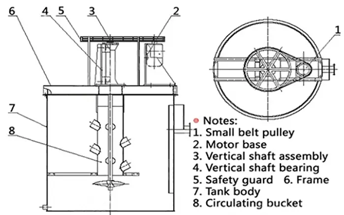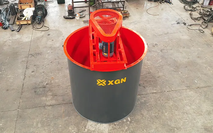
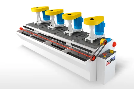
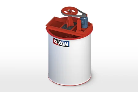
An agitation tank uses a motor-driven impeller to convert mechanical power into fluid movement. The rotating impeller circulates slurry through the tank, keeps solid particles suspended and distributes reagents evenly throughout the mixture.
In mineral processing, agitation tanks are commonly installed before flotation, during leaching, in reagent preparation systems and between processing stages where consistent slurry density is required.
Quick answer: The motor and gearbox rotate a shaft and impeller. The impeller produces axial and radial flow, while tank baffles prevent uncontrolled swirling. Together, these movements circulate the slurry from top to bottom, suspend ore particles and improve contact between solids, liquids and reagents.
For continuous mineral-processing duties, XINGAONAI’s high-efficiency agitation tank is designed for slurry mixing, reagent conditioning and leaching applications.
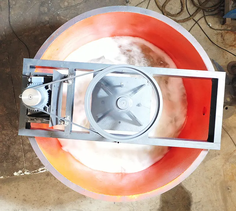
Main Components Involved in the Working Process
Understanding the following components makes the agitation process easier to visualize.
| Component | Function in the agitation process |
|---|---|
| Motor | Supplies mechanical power |
| Gearbox | Adjusts rotational speed and increases torque |
| Coupling | Transfers power from the drive to the shaft |
| Shaft | Transfers torque to the impeller |
| Impeller | Generates slurry flow and suspension force |
| Baffles | Reduce swirling and redirect slurry vertically |
| Tank body | Contains the slurry and defines the circulation space |
| Inlet and outlet | Control material feeding and discharge |
For a more detailed explanation of mixer components and equipment selection, see the tank agitator mixer guide.
How an Agitation Tank Works Step by Step
1. Slurry Enters the Tank
Ground ore slurry, process water or reagent solution enters through the feed connection. Depending on the process, the tank may operate as a batch system or receive material continuously.
In mineral processing, the feed normally contains fine mineral particles that have already passed through crushing and grinding. Because these particles have different sizes and densities, they may begin to settle if circulation is insufficient.
2. The Motor Drives the Impeller
When the agitation system starts, the motor transmits power through the gearbox and coupling to the vertical shaft. The shaft then rotates the impeller at the required operating speed.
The gearbox provides the torque needed to move the slurry. Dense slurry and coarse particles generally require more torque than clean water or low-density liquid.
The correct speed depends on:
Tank diameter and liquid depth
Impeller diameter and blade angle
Slurry density
Solids concentration
Particle size
Liquid viscosity
Required mixing duty
Operating at a higher speed does not always improve mixing. Excessive speed may increase energy consumption, wear, vibration and air entrainment.
3. The Impeller Creates Fluid Movement
As the impeller rotates, its blades accelerate the surrounding slurry. This produces a pressure difference around the impeller and creates circulation within the tank.
Two main flow directions may be generated:
Axial flow: Slurry moves parallel to the shaft, either upward or downward. This flow is important for top-to-bottom circulation and solids suspension.
Radial flow: Slurry moves outward from the impeller toward the tank wall. It can provide stronger local turbulence and reagent dispersion.
Most mineral-slurry mixing systems use a combination of axial and radial flow.
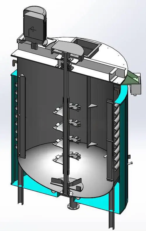
4. Baffles Control the Flow Pattern
If a cylindrical tank has no baffles, the liquid may simply rotate around the shaft and form a vortex. In this condition, the entire slurry mass turns as one body, but top-to-bottom mixing can remain weak.
Baffles interrupt this circular movement and redirect the slurry into a more useful circulation loop.
A typical flow cycle is:
The impeller pushes slurry downward or outward.
Slurry travels across the tank bottom.
The flow rises along the tank wall.
Slurry returns toward the impeller.
The circulation cycle repeats continuously.
This pattern reduces stagnant areas and distributes solids and reagents through the working volume.
5. Solid Particles Are Lifted and Suspended
Mineral particles naturally settle under gravity. The agitation system must generate enough upward and horizontal flow to counteract their settling velocity.
When circulation is adequate, particles remain distributed throughout the liquid instead of forming a compact bed at the bottom.
The objective is not necessarily to create maximum turbulence. It is to reach a stable suspension condition in which:
Solids do not accumulate rapidly at the bottom
Slurry density remains reasonably uniform
Reagents can contact mineral particles
The tank can discharge consistently
Power consumption remains controlled
The speed at which all particles become mobilized from the tank bottom is often described as the just-suspended condition. Its exact value depends on particle and equipment characteristics.
6. Reagents Are Distributed Through the Slurry
Reagents may be introduced through a separate feed point or together with the slurry. The circulation created by the impeller carries these chemicals throughout the tank.
In flotation conditioning, this process helps collectors, activators, depressants and pH modifiers contact the mineral surfaces before the slurry enters the flotation machine.
In a leaching circuit, agitation improves contact between the ore particles and the leaching solution. This supports a more uniform chemical environment, although recovery also depends on mineralogy, particle liberation, reagent concentration, temperature and retention time.
7. The Conditioned Slurry Leaves the Tank
In a continuous system, conditioned slurry exits through an overflow or discharge connection while new slurry enters the tank. The liquid level and feed rate determine the actual residence time.
A simplified preliminary relationship is:
Average residence time = effective tank volume ÷ slurry flow rate
Actual residence-time distribution may differ because of short-circuiting, dead zones and process fluctuations. Tank geometry and inlet/outlet positions therefore matter as much as nominal capacity.
The discharged slurry may then move to flotation, leaching, filtration, separation or another conditioning stage.
Batch and Continuous Agitation
Batch Operation
In batch operation, a fixed amount of material enters the tank, mixes for a specified period and is then discharged.
Batch mixing is suitable for:
Reagent preparation
Small test plants
Intermittent processing
Applications requiring a defined mixing time
Continuous Operation
In continuous operation, slurry enters and leaves the tank while the impeller keeps running.
This arrangement is commonly used for:
Flotation feed conditioning
Continuous leaching circuits
Slurry homogenization
pH adjustment
Large mineral-processing plants
Continuous tanks must be designed to minimize short-circuiting, where part of the incoming slurry reaches the outlet without receiving sufficient mixing time.
What Determines Agitation Efficiency?
Impeller Type and Diameter
A larger impeller generally moves more slurry at a given speed, but it also requires more torque. Blade shape determines whether the impeller produces mainly axial flow, radial flow or higher shear.
Impeller Position
If the impeller is too high, solids may accumulate beneath it. If it is too close to the tank bottom, circulation may become restricted or cause excessive local wear.
Deep tanks may require more than one impeller.
Slurry Density and Solids Concentration
Dense slurry is more difficult to circulate and may place greater load on the motor, gearbox and shaft. Changes in solids concentration can alter power consumption and suspension performance.
Particle Size and Density
Large or high-density particles settle faster and require stronger circulation. Maximum particle size is therefore an important operating parameter.
Tank Geometry
Tank diameter, liquid depth, bottom shape and baffle arrangement determine how the flow moves through the vessel. Poor geometry may produce dead zones even if sufficient motor power is installed.
Operating Speed
Low speed may allow solids to settle. Excessive speed may cause:
Higher energy consumption
Faster impeller wear
Shaft vibration
Vortex formation
Air entrainment
Slurry splashing
The correct speed is the lowest practical speed that consistently meets the process requirement.
For detailed engineering considerations, read the tank agitator design guide.
How Agitation Tanks Work in Different Mining Processes
Flotation Conditioning
The tank suspends ground ore and distributes flotation reagents before the slurry enters the flotation cells. Stable mixing improves reagent contact and helps maintain consistent feed conditions.
Gold and Silver Leaching
Agitation circulates ore particles through the leaching solution and reduces stagnant regions. Multiple tanks may be arranged in series to provide the required overall residence time.
Copper and Zinc Leaching
For acidic or otherwise corrosive slurry, the operating principle remains mechanical circulation, but tank lining and wetted-component materials must suit the chemical environment.
Reagent Preparation
Water and concentrated or dry reagents are mixed to produce a consistent dosing solution. The system should avoid undissolved material and local over-concentration.
Slurry Homogenization
An agitation tank can reduce short-term variations in slurry density or reagent concentration before the next processing stage.
Signs That an Agitation Tank Is Working Correctly
A properly operating tank normally shows:
Stable slurry circulation
No persistent stationary region at the bottom
Uniform slurry density at different sampling points
Stable motor current
Acceptable vibration and noise
No severe central vortex
Consistent outlet concentration
Predictable downstream process performance
Surface movement alone does not prove that bottom solids are fully suspended. Inspection, sampling or density measurement at different positions may be required.
Common Causes of Poor Agitation
Solids Accumulating at the Bottom
Possible causes include insufficient speed, an undersized impeller, excessive solids concentration, coarse particles or incorrect impeller clearance.
Strong Vortex but Weak Vertical Mixing
The tank may lack suitable baffles, or the impeller may be producing too much rotational flow and insufficient axial circulation.
High Motor Current
Possible causes include increased slurry density, an obstructed impeller, bearing problems, settled solids or incorrect operating speed.
Excessive Vibration
Check shaft alignment, impeller balance, bearing condition, structural support and accumulated material on the blades.
Uneven Reagent Distribution
Review the reagent addition point, mixing time, circulation pattern and inlet/outlet arrangement.
These symptoms should be evaluated against the original equipment design. Increasing rotational speed without identifying the cause may damage the drive system or accelerate wear.
Conclusion
An agitation tank works by transferring motor power through a gearbox and shaft to an impeller. The impeller generates controlled circulation, while baffles direct the flow through the entire tank.
In mineral processing, this movement keeps ore particles suspended, distributes flotation or leaching reagents and maintains more consistent feed conditions for downstream equipment.
Effective operation depends on matching the impeller, speed, motor power and tank geometry to the actual slurry properties. Simply increasing speed or motor power cannot correct an unsuitable tank or impeller design.
For equipment configuration based on slurry density, particle size, throughput and process requirements, review XINGAONAI’s high-efficiency agitation tank for mineral processing.