Tank agitator design determines whether a mixing system can keep mineral particles suspended, distribute reagents evenly and provide the required residence time without excessive power consumption or mechanical wear.
A suitable design must consider the entire system—not only the motor. Tank geometry, working volume, slurry properties, impeller type, impeller diameter, rotational speed, baffles, shaft strength and construction materials all influence performance.
Quick answer: Start by defining the mixing duty and slurry properties. Calculate the required working volume from flow rate and retention time, select an appropriate tank geometry and impeller, estimate flow and power requirements, check solids suspension, and then verify the shaft, gearbox, bearings and construction materials.
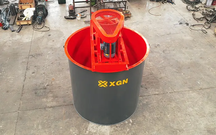
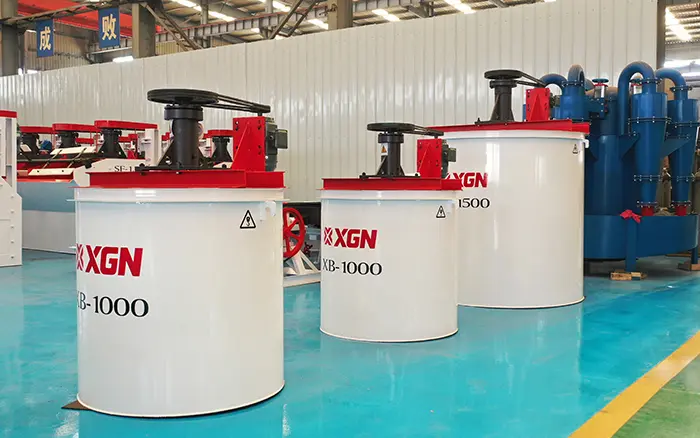
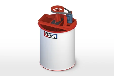
XINGAONAI’s high-efficiency agitation tank is intended for slurry conditioning, reagent mixing and leaching applications in mineral-processing plants.
Define the Mixing Objective First
The design process must begin with a clear process objective. Different duties require different flow patterns, speeds and power inputs.
Common mining applications include:
Keeping ground ore particles suspended
Mixing flotation reagents with slurry
Maintaining uniform slurry density
Preparing and diluting process reagents
Increasing contact during leaching
Adjusting pH before flotation or separation
Preventing sedimentation during temporary storage
Equalizing feed before downstream equipment
A mixer designed primarily for liquid blending may not provide enough bottom velocity to suspend dense mineral particles. Likewise, a high-shear design may consume unnecessary power when the objective is only bulk circulation.
Design Information Required
Before selecting the tank or agitator, collect the following information.
| Design input | Information required |
|---|---|
| Process duty | Suspension, blending, conditioning, leaching or storage |
| Flow rate | Normal, minimum and maximum slurry feed rate |
| Retention time | Required average process time |
| Slurry density | kg/m³ or t/m³ |
| Solids concentration | Percentage by weight or volume |
| Particle size | Maximum size and particle-size distribution |
| Particle density | Specific gravity of the mineral solids |
| Viscosity | At actual operating concentration and temperature |
| Chemistry | pH, reagent type and corrosiveness |
| Temperature | Normal and maximum operating temperature |
| Operating mode | Batch or continuous |
| Site conditions | Power supply, altitude, ambient temperature and installation space |
Using only tank volume or motor power is not sufficient for reliable design.
Step 1: Calculate the Required Working Volume
For a continuous process, the initial working volume can be estimated from slurry flow rate and required residence time:
V = Q × t
Where:
V = required effective working volume
Q = slurry volumetric flow rate
t = required average residence time
For example, if the slurry flow is 30 m³/h and the required average retention time is 20 minutes:
V = 30 × 20/60 = 10 m³
This is the theoretical process volume. The final tank size may need additional allowance for:
Freeboard
Feed fluctuations
Foam formation
Internal components
Effective versus geometric volume
Short-circuiting
Level-control range
Maintenance requirements
For several tanks installed in series, divide the required overall residence time across the individual tanks while accounting for transfer and usable volume.
Step 2: Determine Tank Geometry
A vertical cylindrical tank is commonly used for mineral slurry because it supports predictable circulation and is easier to manufacture and line.
Important dimensions include:
Tank diameter, T
Normal liquid height, H
Total tank height
Impeller diameter, D
Impeller clearance above the bottom, C
Baffle width
Distance between multiple impellers
Many preliminary layouts begin with a liquid-height-to-tank-diameter ratio near 1:1. However, there is no universal H/T ratio for every mineral slurry.
A tall, narrow tank may need:
A longer shaft
Greater shaft stiffness
More than one impeller
Additional structural support
Careful vibration analysis
A very wide, shallow tank may require:
A larger impeller
Greater torque
More attention to bottom circulation
Multiple agitation points in extreme cases
Final geometry should be selected around the required process volume and circulation pattern rather than an arbitrary dimensional ratio.
Step 3: Select the Impeller Type
The impeller must generate the flow pattern required by the process.
| Impeller type | Main characteristic | Typical mining duty |
|---|---|---|
| Pitched-blade turbine | Combined axial and radial flow | General slurry conditioning and suspension |
| Hydrofoil impeller | High axial flow at relatively low shear | Large-volume circulation and efficient suspension |
| Flat-blade radial turbine | Strong radial flow and local turbulence | Reagent dispersion and intensive mixing |
| Paddle impeller | Simple, moderate circulation | Reagent preparation and lower-intensity mixing |
| Multi-stage impellers | Circulation at different liquid levels | Deep tanks and high H/T ratios |
| Anchor impeller | Wall-sweeping movement | Very viscous liquids; not the normal first choice for mineral slurry |
For solids suspension, axial-flow impellers are often preferred because they produce strong vertical circulation. However, the final choice depends on settling velocity, tank geometry and process purpose.
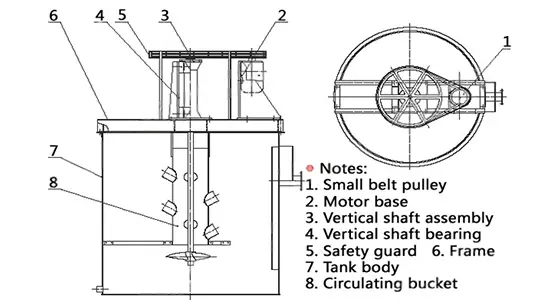
The tank agitator mixer selection guide explains the main mixer components and impeller configurations in more detail.
Step 4: Select the Impeller Diameter
Impeller diameter is normally expressed relative to tank diameter:
D/T = impeller diameter ÷ tank diameter
For many mechanically agitated tanks, preliminary impeller diameters fall within roughly 25%–50% of the tank diameter. This is only an initial range—not a final selection rule.
A larger impeller generally:
Pumps more slurry at the same speed
Requires more torque
Can operate at a lower rotational speed
May improve bulk circulation
Increases shaft and gearbox load
A smaller impeller generally:
Requires a higher rotational speed for equivalent circulation
Produces more localized mixing
May be less effective at moving slurry through a large tank
Can increase wear when operated at excessive tip speed
The final diameter should be selected using the impeller manufacturer’s flow number and power number data.
Step 5: Set the Impeller Position
The bottom clearance is the vertical distance between the tank bottom and the lowest impeller.
If the impeller is too high:
Dense solids may settle below the circulation zone
A stationary bed may form
Restarting the mixer may become difficult
Effective tank volume may decrease
If the impeller is too low:
Flow may be restricted by the tank bottom
Local abrasion may increase
The impeller may recirculate slurry within a small region
Maintenance access may become more difficult
The optimum clearance depends on impeller type, diameter, bottom shape and solids characteristics. For deep tanks, additional impellers may be installed along the shaft to maintain circulation at different elevations.
Step 6: Design the Baffles
Without baffles, slurry inside a cylindrical tank may rotate around the shaft and form a central vortex. This motion can look vigorous at the surface while providing weak top-to-bottom mixing.
Baffles interrupt tangential rotation and redirect the flow into axial and radial circulation.
A conventional preliminary arrangement often uses four vertical baffles spaced evenly around the tank wall. A starting baffle width of approximately one-tenth of the tank diameter is common in general mixing practice, but mineral-slurry service may require adjustment for:
Abrasion
Scale buildup
Structural strength
Tank lining
Cleaning access
Solids accumulation behind the baffles
Baffles should not create inaccessible pockets where dense particles can accumulate.
Step 7: Estimate Reynolds Number
The impeller Reynolds number helps identify whether the flow around the impeller is laminar, transitional or turbulent:
Re = ρND² / μ
Where:
Re = impeller Reynolds number
ρ = slurry density
N = impeller rotational speed in revolutions per second
D = impeller diameter
μ = dynamic viscosity
In turbulent operation, inertial forces dominate and impeller power number becomes comparatively stable. In transitional or laminar operation, viscosity has a much greater influence on mixing and power demand.
Mineral slurries may also be non-Newtonian, meaning viscosity changes with shear rate. When this occurs, a single laboratory viscosity value may not represent actual tank conditions.
Step 8: Estimate Impeller Power
For turbulent mixing, impeller power is commonly estimated using:
P = Np × ρ × N³ × D⁵
Where:
P = power transferred to the fluid
Np = impeller power number
ρ = slurry density
N = impeller speed in revolutions per second
D = impeller diameter
The equation shows that power is highly sensitive to both rotational speed and impeller diameter:
Power changes approximately with the cube of speed
Power changes approximately with the fifth power of impeller diameter
Therefore, a relatively small design change can produce a large change in power demand.
The power number is not universal. It depends on:
Impeller geometry
Blade angle
Number of blades
Reynolds number
Baffle arrangement
Impeller-to-tank diameter ratio
The selected motor must also allow for gearbox losses, mechanical losses, startup conditions and a suitable service factor. Fluid power should not be treated as identical to motor nameplate power.
Step 9: Estimate Pumping Capacity
The circulation generated by an impeller can be described using the flow number:
Qp = Nq × N × D³
Where:
Qp = impeller pumping rate
Nq = impeller flow number
N = rotational speed
D = impeller diameter
A high-flow impeller can circulate a large volume of slurry without necessarily producing high shear.
Both power number and flow number should come from tested data for the selected impeller design. Generic values from a different impeller should not be used for final equipment sizing.
Step 10: Check Solids Suspension
For mineral slurry, the design must verify whether the circulation is sufficient to prevent excessive solids accumulation.
Important suspension variables include:
Particle diameter
Particle density
Liquid density
Solids concentration
Liquid viscosity
Impeller type
Impeller diameter
Bottom clearance
Tank diameter
The required just-suspended speed is the point at which particles no longer remain stationary on the tank bottom for extended periods.
Operating far below this condition can cause sedimentation. Operating far above it may waste power and increase wear without providing meaningful process improvement.
For coarse, dense or highly concentrated slurry, suspension should be verified through one or more of the following:
Laboratory testing
Pilot-scale testing
Previous operating data
Vendor suspension correlations
Computational fluid dynamics
Full-scale performance guarantees
Step 11: Check Impeller Tip Speed
Impeller tip speed can be calculated as:
Tip speed = πDN
Where:
D = impeller diameter
N = rotational speed in revolutions per second
High tip speed can increase:
Blade abrasion
Slurry erosion
Shear
Air entrainment
Vibration
Power consumption
For abrasive mineral slurry, the design should prioritize sufficient circulation at a reasonable tip speed rather than simply using a small impeller at very high RPM.
Step 12: Design the Shaft and Drive System
The shaft must transmit torque while resisting bending, fatigue and vibration.
Mechanical design checks should include:
Maximum operating torque
Startup torque
Shaft bending
Critical speed
Impeller hydraulic load
Shaft deflection
Coupling alignment
Bearing load
Gearbox service factor
Support-frame rigidity
Long shafts and multiple impellers require particular attention to critical speed and lateral vibration.
The drive system may include:
Electric motor
Gear reducer
Flexible coupling
Upper bearing assembly
Variable-frequency drive
Backstop or overload protection where required
A variable-frequency drive can provide operating flexibility, but it cannot correct an undersized shaft, unsuitable impeller or poorly designed tank.
Step 13: Select Construction Materials
Material selection depends on both abrasion and corrosion.
| Operating condition | Possible construction approach |
|---|---|
| Mild, non-corrosive slurry | Carbon-steel tank and suitable wear-resistant impeller |
| Abrasive mineral slurry | Replaceable rubber, polyurethane or wear-resistant liners |
| Acidic slurry | Rubber lining, compatible coating or corrosion-resistant alloy |
| Cyanide leaching | Materials selected according to chemical compatibility and plant standards |
| Chloride-containing solution | Carefully selected stainless steel or alloy after corrosion review |
| High-wear impeller duty | Replaceable coated or wear-resistant blades |
Material compatibility must be evaluated using actual reagent concentration, pH, temperature and mineral abrasiveness.
“Stainless steel” alone does not guarantee adequate corrosion or abrasion resistance.
Step 14: Position the Inlet and Outlet
Poor inlet and outlet placement can cause short-circuiting, where newly fed slurry travels directly to the outlet without receiving sufficient mixing time.
Good layout should:
Introduce feed into an active circulation zone
Avoid directing feed immediately toward the outlet
Minimize stagnant regions
Maintain stable liquid level
Allow sampling of representative slurry
Provide access for draining and cleaning
For tanks installed in series, the intertank flow arrangement should support the required residence-time distribution.
Preliminary Design Checklist
Before finalizing a tank agitator design, confirm:
The mixing objective is clearly defined.
Normal and maximum flow rates are known.
The working volume provides adequate residence time.
Slurry density and solids concentration are verified.
Maximum particle size and mineral density are known.
Tank geometry supports complete circulation.
Impeller type matches the process duty.
Bottom clearance is suitable for solids suspension.
Baffles reduce vortexing without trapping solids.
Power is calculated using appropriate impeller data.
The motor and gearbox include suitable operating margins.
Shaft strength and critical speed have been checked.
Materials resist the expected abrasion and corrosion.
Inlet and outlet positions limit short-circuiting.
Maintenance access is included in the layout.
Common Tank Agitator Design Mistakes
Selecting the Motor Before the Impeller
Motor power should follow the hydraulic design. Choosing a motor first and then fitting an arbitrary impeller can result in poor circulation or excessive loading.
Designing from Tank Volume Alone
Tanks of equal volume may require very different agitation systems because of particle size, density, viscosity and process objective.
Treating Slurry Like Clean Water
Mineral slurry creates greater torque, abrasion and settling risk than water. Water-test performance may not represent actual operating conditions.
Assuming More RPM Means Better Mixing
Increasing speed raises power demand rapidly and may accelerate wear. Correct impeller diameter and flow pattern are often more important than maximum RPM.
Ignoring the Tank Bottom
A tank can appear well mixed at the surface while solids accumulate below the impeller. Bottom flow and off-bottom clearance must be evaluated.
Copying a Small Tank Directly to a Larger Scale
Geometric similarity does not guarantee equal mixing performance. Power, circulation, tip speed, torque and suspension behavior do not all scale at the same rate.
Ignoring Maintenance Access
The motor, gearbox, shaft and impeller must be removable without dismantling major plant structures wherever practical.
When Is CFD or Pilot Testing Necessary?
Computational fluid dynamics or physical testing is especially valuable when:
The slurry contains coarse or very dense particles
Solids concentration is high
The tank geometry is unusual
Several impellers are installed
Internal coils or structures obstruct flow
Short-circuiting would affect recovery
The design is being scaled significantly
Power or performance guarantees are required
No reliable reference installation exists
CFD can identify probable dead zones and compare flow patterns, but its accuracy depends on the selected slurry model and input data. It should support—not replace—engineering judgment and operating evidence.
Conclusion
Tank agitator design is a system-level engineering task. Reliable performance depends on matching tank geometry, impeller type, impeller diameter, operating speed, power, baffles, shaft design and construction materials to the actual slurry and process duty.
Preliminary formulas can estimate working volume, Reynolds number, pumping capacity and fluid power, but final equipment selection requires impeller-specific data and mechanical verification.
To understand the operating process before beginning the design, read How Does an Agitation Tank Work?. For component and equipment selection, refer to the tank agitator mixer guide.
For mineral-processing equipment selection, review XINGAONAI’s high-efficiency agitation tank for slurry conditioning and leaching.