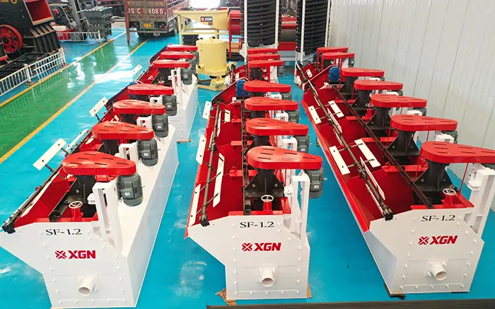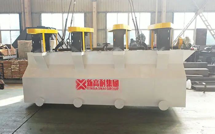
Stable slurry circulation, aeration and froth removal depend not only on operating conditions but also on the mechanical condition of the flotation equipment. Wear of the impeller, stator, shaft, bearings, scraper mechanism or tank can reduce air dispersion, disturb slurry circulation, increase vibration and eventually cause unplanned shutdowns.
This guide focuses on the main parts of an SF-type mechanical agitation flotation machine, including their functions, common wear signs, inspection points and the information required when ordering replacement parts.
Component arrangements vary among flotation machine models and manufacturers. Dimensions, materials and installation clearances should therefore be confirmed from the equipment drawing or the manufacturer’s technical documentation.
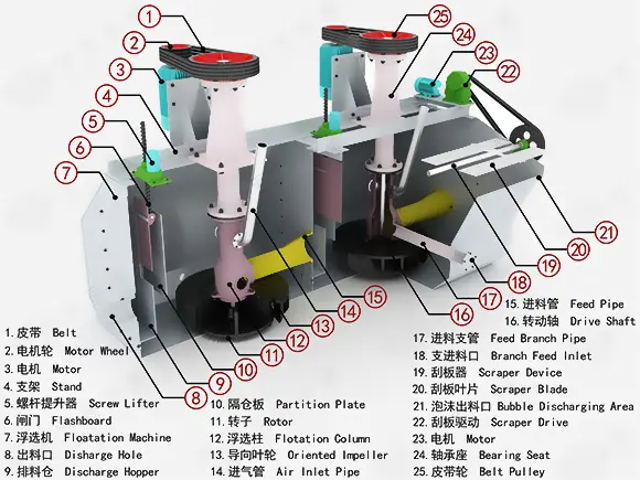
What Are the Main Parts of a Flotation Machine?
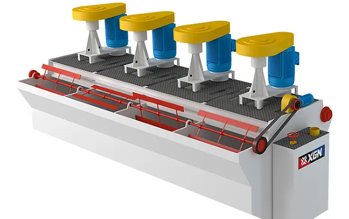
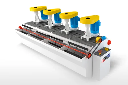
A mechanical flotation machine normally consists of an agitation and aeration assembly, transmission components, a flotation tank, a froth removal system and slurry-control components.
The exact configuration differs between models, but the following flotation parts normally require the most attention during inspection and spare-parts planning.
| Component | Main function | Common warning signs |
|---|---|---|
| Impeller | Agitates slurry, creates circulation and disperses air | Reduced aeration, vibration and weaker agitation |
| Stator or cover plate | Stabilizes flow and works with the impeller to disperse air | Uneven wear, abnormal turbulence and loose fasteners |
| Main shaft | Transfers power from the drive to the impeller | Runout, noise and uneven component wear |
| Bearing assembly | Supports the shaft and maintains stable rotation | High temperature, noise and lubricant leakage |
| Drive system | Drives the shaft and agitation assembly | Unstable speed, belt slippage and coupling problems |
| Froth scraper | Transfers mineralized froth into the concentrate launder | Uneven scraping, froth accumulation or missed froth |
| Tank and lining | Contains the slurry and resists abrasion and corrosion | Wall thinning, corrosion and leakage |
| Air inlet components | Control air entering the agitation zone | Blockage, leakage and unstable aeration |
1. Impeller
The impeller is the main moving component in the agitation and aeration assembly. The motor drives the shaft and impeller, causing the slurry to circulate inside the cell while dispersing the induced air into bubbles.
Because the impeller continuously operates in a slurry containing solid mineral particles, it is exposed to abrasion, erosion and chemical corrosion. Wear may accelerate when the ore is highly abrasive, the feed contains coarse particles or the pulp density is relatively high.
Common impeller wear signs include:
Thinning or deformation of blade edges;
Grooves, chips or cracks on the impeller surface;
Peeling of rubber or polyurethane protection;
Exposure of the metal base;
Uneven wear between individual blades;
Increasing vibration or operating noise.
When the original impeller geometry changes, its ability to circulate slurry and disperse air may decline.
However, reduced aeration does not always mean that the impeller must be replaced. The stator, air inlet, rotational speed and slurry conditions should also be checked before identifying the impeller as the source of the problem.
2. Stator or Cover Plate
The stator is a stationary component that works with the rotating impeller. It reduces excessive rotational flow, directs the slurry and air through the agitation zone and helps maintain a more stable flow pattern.
Common stator problems include:
Thinning or breaking of guide vanes;
Blockage of passages by solids or scale;
Loose or missing fasteners;
Movement away from the correct installation position;
Peeling of protective material;
Changes in the impeller–stator clearance.
The impeller and stator should be inspected as a matched assembly. Even when only one component is replaced, their relative position, concentricity and operating clearance must be checked again.
A universal clearance value should not be applied to every flotation machine. The required clearance varies according to model, impeller diameter and structural design. Always follow the equipment drawing or the manufacturer’s specified value.
3. Main Shaft and Bearing Assembly
The main shaft transfers power from the drive system to the impeller. The bearings support the shaft and keep it rotating in the designed position.
Problems affecting the shaft or bearings may appear as:
Continuously rising bearing temperature;
Regular knocking, grinding or metallic noise;
Increasing machine vibration;
Radial shaft runout;
Lubricant leakage or slurry entering the seal area;
Discolored or contaminated grease;
Uneven impeller wear.
A high bearing temperature does not automatically indicate that the bearing has failed. Insufficient lubrication, excessive grease, incorrect bearing clearance, shaft misalignment and improper belt tension may also generate heat.
During a shutdown inspection, check the lubricant condition, fasteners, bearing clearance, shaft alignment and signs of bending or surface damage.
4. Drive System
The drive system may include the motor, pulleys, belts, coupling or reduction components, depending on the flotation machine model.
Inspection should cover:
Loose motor mounting bolts;
Cracked, glazed or insufficiently tensioned belts;
Misaligned pulleys;
Coupling displacement;
Damaged or missing guards;
Actual operating speed compared with the specified speed.
A drive-system problem can produce an unstable impeller speed. In this condition, slurry circulation and air dispersion may fluctuate even when the impeller and stator are not severely worn.
5. Froth Scraper Mechanism
The froth scraper normally consists of scraper blades, a scraper shaft, a drive assembly, couplings and bearings. Its purpose is to transfer mineralized froth from the cell surface into the concentrate launder.
Common scraper problems include:
Bent or worn scraper blades;
Deformation of the scraper shaft;
Unequal blade heights;
Loose couplings or fasteners;
Unstable scraper speed;
Incorrect contact between the blade and froth layer.
If froth is forming normally but is not entering the concentrate launder consistently, inspect the scraper mechanism before increasing the impeller speed or air supply.
6. Tank, Lining and Concentrate Launder
The flotation tank remains in continuous contact with abrasive mineral particles, water and flotation chemicals. This can cause abrasion, erosion and corrosion.
The feed area, tank bottom, changes in slurry direction and connections between adjacent cells normally require particular attention.
Tank inspection should include:
Local thinning of tank walls;
Blistering, cracking or detachment of the lining;
Leakage around welds;
Accumulated solids on the tank bottom;
Blockage in the concentrate launder;
Uneven overflow edges.
Minor damage may be repaired according to the tank material and maintenance procedure. Structural deformation, continuing leakage or large areas of corrosion should be evaluated by the manufacturer or qualified maintenance personnel instead of being covered by a temporary surface repair.
7. Air Inlet and Adjustment Components
For a self-aspirating flotation machine that uses impeller rotation to generate negative pressure, the air inlet, adjustment valve and relevant seals must remain unobstructed.
When aeration is insufficient, check:
Whether the air pipe is blocked by slurry or scale;
Whether pipe connections are leaking;
Whether the air-adjustment valve is stuck;
Whether the impeller speed is correct;
Whether the impeller and stator remain correctly positioned;
Whether the pulp density has changed significantly.
During normal operation, the impeller creates negative pressure to draw in air while circulating the slurry. The stator stabilizes the flow and helps disperse the incoming air. This interaction is central to how a flotation machine works and explains why blocked air pipes, worn impellers or incorrect installation can directly change the aeration condition.
How Do You Know When Flotation Parts Need Replacement?
Replacement decisions should not be based only on operating hours. Two machines of the same model may experience very different wear rates when processing different ores.
Use the following four types of information together.
1. Dimensional Change
Measure critical dimensions of the impeller, stator, shaft sleeve and lining. Compare the results with new-part dimensions, previous inspection records or the manufacturer’s allowable limits.
2. Visible Damage
Look for cracks, broken sections, severe corrosion, loss of protective material and damaged mounting points. Rotating components with developing cracks should not remain in operation.
3. Operating Condition
Record vibration, noise, bearing temperature, motor current, aeration condition and scraper stability. Persistent deviation from the normal operating range should be followed by a shutdown inspection.
4. Process Performance
Wear may be accompanied by reduced aeration, weaker slurry circulation or uneven froth distribution. However, changes in recovery or concentrate grade may also result from feed size, reagent dosage, pulp density or feed variability.
Mechanical and metallurgical causes should therefore be diagnosed separately. See factors affecting flotation machine efficiency for non-mechanical variables that may produce similar symptoms.
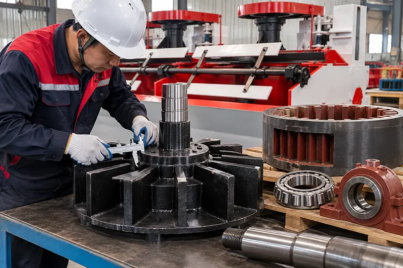
Flotation Parts Inspection Checklist
Daily inspections should cover:
New or unusual operating noise;
Increasing vibration;
Continuously rising bearing temperature;
Fluctuation in motor current;
Stable operation of the froth scraper;
Condition of the air inlet;
Loose fasteners;
Leakage from the tank or pipes.
During planned shutdowns, inspect:
Impeller wear and wear uniformity;
Stator vanes, passages and fasteners;
Relative impeller and stator position;
Main-shaft runout and surface condition;
Bearings, seals and lubrication;
Belts, pulleys and couplings;
Scraper blades, shaft and drive mechanism;
Tank lining and welds.
Keep photographs and measurement records. Comparing several inspections is more useful for predicting replacement intervals than relying on one visual observation.
What Information Is Required When Ordering Flotation Parts?
Providing only the phrase “flotation impeller” is normally insufficient to identify the correct component. Parts with a similar appearance may have different dimensions, mounting holes, rotation directions and materials.
When requesting a quotation, provide:
Equipment manufacturer;
Complete machine model;
Equipment or serial number;
Required part name;
Original drawing or part number;
Critical installation dimensions;
Number and spacing of mounting holes;
Shaft diameter or connection dimensions;
Part material;
Type of ore being processed;
Clear photographs of the used part;
Required quantity;
Project location.
If the drawing number is unavailable, photograph the complete part, mounting surface, connection points and worn areas with a scale visible in the image. For impellers, stators and rotating components, confirm the rotation direction when necessary.
Conclusion
Effective flotation-parts management does not mean replacing components frequently. It means identifying the parts that are actually affecting machine operation and determining the correct replacement time through dimensional measurements, operating records and shutdown inspections.
The impeller and stator control agitation and air dispersion. The shaft, bearings and drive system maintain stable rotation. The scraper removes mineralized froth, while the tank and lining contain the slurry and protect the machine structure.
When ordering replacements, provide an accurate equipment model, part number, dimensions, material and photographs. This reduces mismatch risk, shortens downtime and helps maintain stable flotation-machine operation.