
A spiral classifier is a key piece of equipment in many mineral processing plants. It works together with a ball mill to form a closed grinding circuit. Its job is to separate fine particles from coarse ones. The fine particles overflow as finished product, while the coarse ones are returned to the mill for more grinding. To keep a spiral classifier running well, you need to know its main parts. This article explains the major spiral classifier parts, what each part does, and how to maintain them.

What Is a Spiral Classifier?
Before we look at the parts, let us quickly review how the machine works.
A spiral classifier has a long, inclined tank. Inside the tank, a spiral shaft rotates slowly. Slurry (a mixture of water and ground ore) enters the tank from the side. Fine particles float and flow over the overflow weir. Coarse particles sink to the bottom. The rotating spiral pushes these coarse particles up the incline to the discharge port. The coarse material then goes back into the ball mill for further grinding.
This simple but effective design relies on several spiral classifier parts working together.
Main Spiral Classifier Parts
A spiral classifier is made up of several main components. Based on common industrial designs, the following parts are essential.
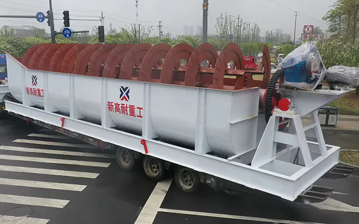
Tank (Trough Body)
The tank is the large metal container that holds the slurry. It has a U-shaped or semicircular cross-section. The tank is usually made of welded steel plates and structural steel. It is installed at an incline, typically at an angle of 12 to 18 degrees. The tank has several openings: a feed inlet on the side, a sand return port near the top, and a drain valve at the bottom. The size and shape of the tank determine the settling area and the classifier's capacity.
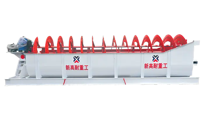
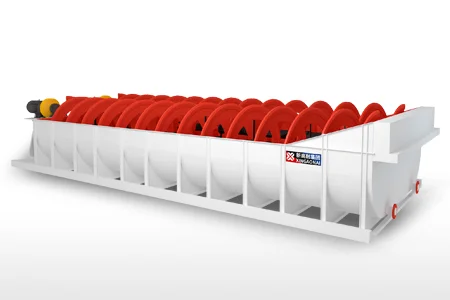
Spiral Shaft and Blades
The spiral shaft is the heart of the classifier. It is a long steel pipe or solid shaft that runs the length of the tank. The shaft is often made of seamless steel pipe or fabricated from steel plates welded together. The shaft must be strong enough to handle heavy loads without bending.
Attached to the shaft are spiral blades (also called flights or screw blades). These blades are shaped like a continuous helix. They are made of wear-resistant materials such as cast iron or high-manganese steel. The spiral blades push the settled coarse particles up the incline to the discharge port. The shape and length of the blades directly affect the grading performance of the machine.
Both single-spiral and double-spiral designs are available. Double-spiral classifiers have two parallel shafts and blades, which provide higher capacity.
Drive Unit (Transmission Device)
The drive unit provides the power to rotate the spiral shaft. It consists of an electric motor and a gear reducer. The reducer slows down the motor speed to a low rotational speed suitable for the spiral. Typical motor power ranges from 2.2 kW for small units up to 22 kW or more for large classifiers. Some modern classifiers use variable frequency drives (VFDs) to adjust the spiral speed. This allows operators to fine-tune the classification process for different materials.
Lifting Mechanism
The lifting mechanism is a very useful feature. It allows the spiral shaft to be raised or lowered. There are two common types: manual (hand-driven) and motor-driven. The lifting device serves several purposes. During startup, the spiral is raised to avoid overload. When the machine is running, the lifting mechanism can be used to adjust the gap between the spiral blades and the bottom of the tank. This adjusts the volume of sand returned and helps control classification accuracy. The lifting device also makes maintenance easier by allowing the spiral to be lifted out of the tank.
Lower Support (Bearing Bush)
The lower support is located at the bottom end of the spiral shaft. It is also called the bearing bush or lower bearing. This part supports the lower end of the shaft and allows it to rotate smoothly. The lower support is often made of cast iron or bronze for durability. It must be well-sealed to prevent sand and slurry from entering the bearing area. If sand gets into the lower support, it can cause rapid wear and even shaft breakage.

Overflow Weir
The overflow weir is a movable baffle plate at the discharge end of the tank. It controls the level of the slurry in the tank. The height of the weir determines how much time the material spends in the settling zone. A higher weir gives more residence time, which produces finer overflow particles. A lower weir produces coarser overflow. The weir can be adjusted by adding or removing wooden boards or by using an adjustable metal plate.
Discharge Valve
The discharge valve is located at the bottom of the tank. It is used to drain the tank when the machine needs cleaning or maintenance. In some designs, the discharge valve also helps control the flow of coarse material.
How the Parts Work Together
All of these spiral classifier parts work as a system. The tank holds the slurry. The drive unit turns the spiral shaft. The spiral blades push coarse solids up the incline. The lifting mechanism allows the spiral to be raised for startup and maintenance. The overflow weir sets the separation size. And the lower support keeps the shaft aligned and rotating smoothly.
If any of these parts fails, the classifier will not perform well. For example, a worn lower support can cause the shaft to wobble, leading to uneven wear on the blades and increased power consumption. A damaged lifting mechanism may prevent the spiral from being raised, making maintenance difficult. Understanding each part helps you diagnose problems and plan repairs.
Common Maintenance and Troubleshooting Tips
Regular inspection of spiral classifier parts can prevent major breakdowns. Here are some common issues and what to check.
Shaft break. The main causes are uneven sand return, poor shaft material, or incorrect installation. Solution: replace or reweld the hollow shaft.
Abnormal vibration or noise. Stop the machine immediately. Check for bent spiral blades, loose bolts, or sand in the lower bearing.
Bent spiral blades. This is often caused by too much sand return or the spiral not being raised high enough before startup. Repair or replace the damaged blades.
Worn gears. Long-term use wears down the gear teeth. Replace damaged gears and maintain the drive unit regularly.
Low overflow or poor classification. Adjust the weir height, check the spiral speed, and verify that the feed rate is within the machine's capacity.
Conclusion
A spiral classifier is a simple but essential machine in mineral processing. Its key parts include the tank, spiral shaft and blades, drive unit, lifting mechanism, lower support, overflow weir, and discharge valve. Each part has a specific job. Knowing these spiral classifier parts helps you operate the machine correctly, perform routine maintenance, and troubleshoot problems quickly. Regular checks of the spiral blades, lower bearing, and lifting mechanism will extend the life of your classifier and keep your grinding circuit running efficiently.