Hydrocyclone pressure normally refers to the feed pressure measured as the slurry enters the hydrocyclone. It affects the velocity of the incoming slurry and influences the internal vortex, processing capacity, cut size, and the condition of the overflow and underflow.
When the pressure is too low, the vortex may not be strong enough to achieve stable separation. When it is excessively high, a finer cut may be possible, but energy consumption and wear on the inlet, liners, cone and apex can increase.
The operating objective is therefore not to generate the highest possible pressure. It is to maintain stable pressure within the range appropriate for the hydrocyclone design, feed properties and required separation result.
1. Where Should Hydrocyclone Pressure Be Measured?
A pressure gauge or transmitter should be installed close to the hydrocyclone feed inlet, preferably after the distribution manifold and before the slurry enters the cyclone.
Pump discharge pressure should not automatically be treated as hydrocyclone feed pressure. Pressure may be lost between the pump and cyclone because of:
Pipe friction
Elbows and valves
Elevation differences
Manifold resistance
Uneven flow distribution between cyclones
In a cyclone cluster, monitoring only the common manifold pressure may not identify a problem affecting one branch. Individual branches should also be checked for blockage, different valve positions and uneven flow distribution.
The gauge range should not be unnecessarily large. Normal pressure should ideally fall near the middle of the gauge range so that smaller changes remain visible.
Slurry can block gauge ports and impulse connections. The diaphragm, pressure port and transmitter should therefore be inspected and cleaned regularly.
2. How Does Pressure Affect Hydrocyclone Classification?
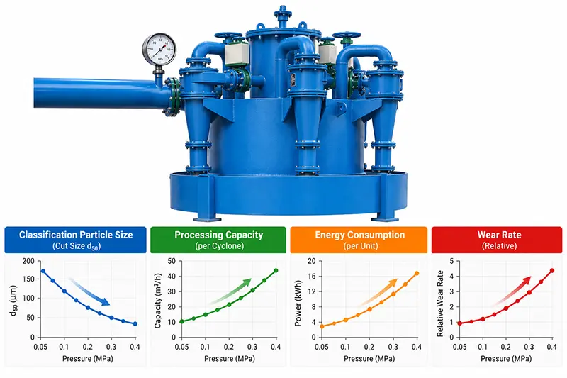
When cyclone geometry, feed density and material characteristics remain approximately constant, increasing the feed pressure generally causes:
Higher slurry velocity at the inlet
Stronger centrifugal action
Increased volumetric throughput
A finer cut size
The possibility of more fine particles reporting to the underflow
Higher pump energy consumption
Faster wear of internal cyclone components
Reducing the pressure generally produces a coarser cut and lower capacity. If the pressure falls below the stable operating range, the internal vortex may become weak or unstable, producing inconsistent overflow and underflow.
The relationship is not purely linear. A change in feed density, viscosity, particle-size distribution, apex wear or inlet condition can change classification performance even when the pressure reading remains the same.
Operators should therefore assess pressure together with the underflow pattern and simultaneous samples of the feed, overflow and underflow.
3. What Is the Correct Hydrocyclone Pressure?
There is no single operating-pressure value suitable for every hydrocyclone.
The required pressure depends on:
Hydrocyclone diameter
Inlet dimensions
Cone geometry
Vortex finder diameter
Apex diameter
Feed solids concentration
Particle size and density
Slurry viscosity
Required cut size
Single-cyclone or cluster arrangement
Some industrial hydrocyclones may operate within a broad range of approximately 30–300 kPa. This range is only an industry reference and must not be used as the automatic setpoint for a particular cyclone.
The correct pressure should be determined from the manufacturer’s performance curves, commissioning results and the required product specification.
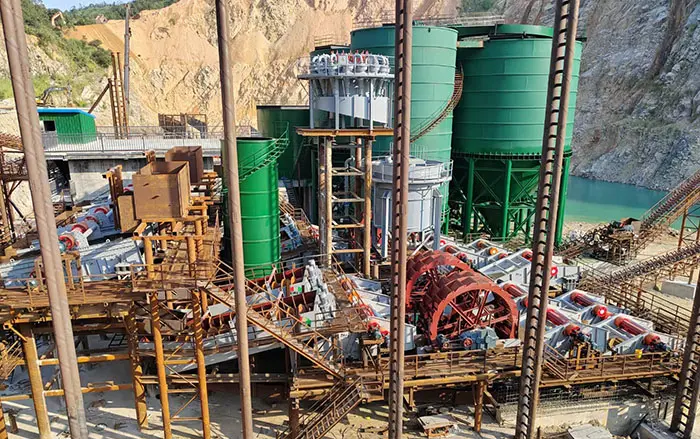
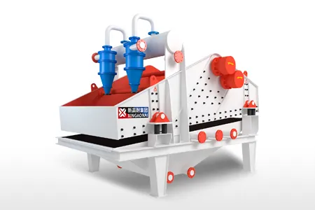
In a fine-sand recovery system, the pressure must also match the pump flow, hydrocyclone size, feed concentration and apex-discharge condition. XINGAONAI’s fine sand recovery machine uses hydrocyclones for fine-sand concentration and separation, but different models use different cyclone arrangements and water-processing capacities. One fixed pressure should not be applied to every model.
4. How to Determine the Appropriate Operating Pressure
Step 1: Stabilize the Feed
Before changing pressure, stabilize the following conditions as far as possible:
Sump level
Feed solids concentration
Feed particle-size distribution
Make-up water
Pump speed
Number of cyclones online
If these conditions continue changing, a pressure change may not originate in the cyclone itself.
Step 2: Establish the Initial Pressure
Start with the pressure recommended by the equipment manufacturer. Allow the flow, pressure and underflow to stabilize.
Record:
Feed pressure
Pump speed or variable-frequency drive setting
Motor current
Feed solids concentration
Underflow concentration
Overflow and underflow particle sizes
Apex-discharge pattern
Step 3: Make Small Adjustments
Adjust pump speed in small increments through the variable-frequency drive. Change only one operating variable at a time.
After every adjustment, allow the system to stabilize before collecting samples.
Do not change pump speed, dilution water and apex diameter simultaneously. Otherwise, it becomes difficult to identify which adjustment produced the result.
Step 4: Set Pressure According to the Product Result
A suitable operating pressure should satisfy several conditions:
Required throughput is achieved.
Overflow and underflow particle sizes meet the target.
Underflow discharge remains stable.
The pump does not cavitate or overload.
Energy use remains reasonable.
Cyclone wear remains acceptable.
The pressure reading is not the final objective. Stable classification performance is the actual objective.
5. Low Hydrocyclone Pressure: Symptoms and Causes
Common symptoms
Pressure below the normal operating baseline
Weak or intermittent underflow
Coarse particles reporting to the overflow
Coarser cut size
Reduced capacity
Failure to establish stable pressure
Possible causes
Pump speed is too low.
The pump impeller is worn.
Sump level is too low.
The pump is drawing air.
The suction line is leaking.
Feed volume is insufficient.
The pipe or pump inlet is blocked.
A bypass valve is too far open.
Too many cyclones are online.
The pressure gauge is blocked or inaccurate.
Corrective sequence
Check the pressure gauge first. Then inspect the sump level, suction line and pump condition.
After confirming that there is no air ingress, blockage or mechanical pump problem, the pump speed can be increased gradually if the motor and pump operating limits permit it.
Do not make a large pump-speed increase before confirming the feed conditions. Doing so can overload the pump or accelerate cyclone wear.
6. High Hydrocyclone Pressure: Symptoms and Causes
Common symptoms
Pressure above the normal operating baseline
Increased motor current or power consumption
Accelerated wear at the inlet and liners
More fine particles in the underflow
Changes in vibration or operating noise
A sudden pressure increase without a corresponding increase in throughput
Possible causes
Pump speed is too high.
Too few cyclones are online.
A feed valve has changed position.
The inlet or cyclone interior is partially blocked.
The apex is blocked.
Feed solids concentration has changed suddenly.
The installed cyclone or inlet size is unsuitable.
The pressure transmitter has drifted.
High pressure does not automatically indicate good classification.
If the pressure rises suddenly while the underflow rate decreases, inspect for blockage before changing the pump speed.
Before opening or inspecting a hydrocyclone, stop the pump, isolate the valves and release all system pressure.
7. Why Does Hydrocyclone Pressure Fluctuate?
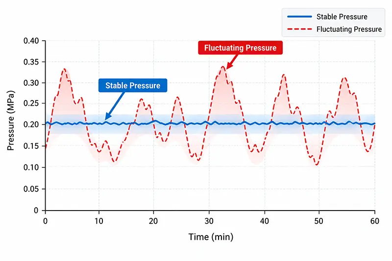
Stable pressure is generally more important than simply maintaining a high pressure reading.
Repeated pressure fluctuations may result from:
Changing sump level
Unstable feed concentration
Changing make-up water flow
Air entering the pump suction
Pump cavitation
Intermittent pipe blockage
Oversized particles entering the cyclone
Unstable variable-frequency drive or control settings
Cyclones being repeatedly opened or closed
Intermittently blocked pressure-gauge ports
If pressure changes follow changes in sump level, stabilize the level and make-up water first.
If the gauge needle moves sharply while the process flow and underflow remain unchanged, inspect the pressure port and gauge before making process adjustments.
8. What If Pressure Is Normal but Separation Is Poor?
A normal pressure reading does not guarantee correct classification.
If overflow or underflow quality is unacceptable while the pressure appears normal, inspect the following conditions.
Feed solids concentration
Excessively high feed concentration increases slurry viscosity and particle interference. It generally produces a coarser cut and may cause roping.
Apex wear
As the apex wears larger, more slurry can enter the underflow. Underflow concentration may decrease and the separation result can change.
Apex too small or blocked
Insufficient discharge capacity can cause roping, internal solids accumulation and abnormal wear.
Worn or blocked vortex finder
The diameter and condition of the vortex finder affect flow split and classification.
Changing feed-size distribution
A change in the proportion of coarse and fine particles can alter both products even if pressure remains unchanged.
Inlet or liner wear
Wear changes the cyclone’s internal geometry and flow field. The inlet, liners, cone and apex should be inspected according to their actual service history.
9. Using the Underflow Pattern as a Diagnostic Tool
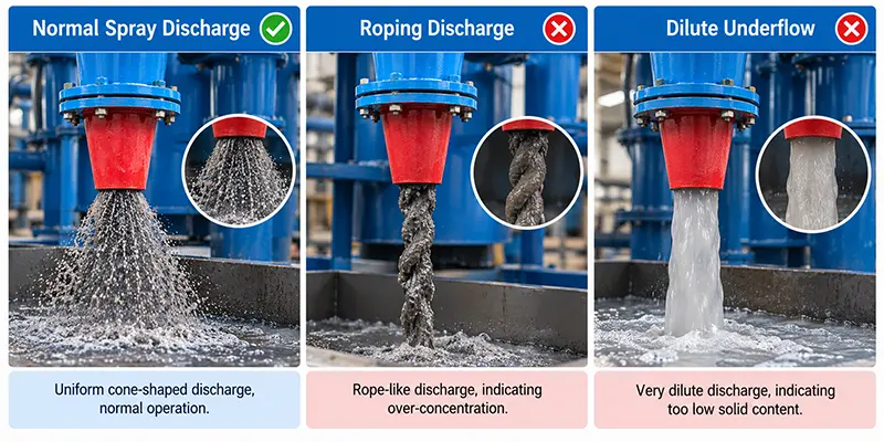
The underflow pattern provides an important visual indication of cyclone condition.
Stable spray discharge
A stable spray pattern with a visible discharge angle usually indicates that the apex is open and discharging. Product quality must still be confirmed through sampling.
Roping
A narrow, rope-like stream can indicate:
Excessive solids loading
An apex that is too small
Partial apex blockage
Excessively high feed concentration
Cyclone overload
Roping should not be corrected by changing pressure alone. Feed concentration, solids rate and apex condition must also be checked.
Excessively dilute underflow
A very dilute underflow may result from an oversized apex, low feed concentration or an unsuitable pressure-and-flow balance.
10. Hydrocyclone Pressure Troubleshooting Table
| Condition | Check first | Do not immediately |
|---|---|---|
| Pressure remains low | Sump level, suction leaks, pump impeller, pump speed and valves | Increase pump speed sharply |
| Pressure rises suddenly | Inlet, apex, vortex finder and pipe blockage | Continue increasing pressure |
| Pressure repeatedly fluctuates | Sump level, density, air ingress, cavitation and gauge port | Change several variables together |
| Pressure normal but overflow is too coarse | Feed density, particle-size distribution and internal wear | Judge performance from pressure alone |
| Pressure normal but underflow is roping | Solids loading, apex size and blockage | Change only the pressure |
| Uneven pressure in a cyclone cluster | Branch valves, manifold distribution and individual blockage | Adjust only common manifold pressure |
11. Daily Monitoring Recommendations
Record the following information during each shift:
Hydrocyclone inlet pressure
Pressure fluctuation range
Pump speed or variable-frequency drive setting
Motor current
Sump level
Feed solids concentration
Underflow-discharge condition
Overflow and underflow sample results
Apex and liner inspection condition
After a stable operating baseline has been established, abnormal changes can be identified much earlier.
In aggregate and sand processing systems, hydrocyclones commonly operate with washing, fine-sand recovery and dewatering equipment. The complete equipment arrangement is discussed in sand washing plant design. This page remains focused specifically on pressure control and does not duplicate the full washing process.
Conclusion
Hydrocyclone pressure is not a parameter that should simply be maximized.
Higher feed pressure can increase throughput and produce a finer cut, but it may also increase energy consumption and equipment wear. Low pressure can weaken the vortex, while fluctuating pressure frequently indicates unstable sump level, feed concentration, pump suction or process control.
A reliable adjustment procedure is to:
Verify pressure-gauge accuracy.
Stabilize sump level, feed density and feed conditions.
Inspect the pump, piping and cyclone for blockage or wear.
Adjust only one variable at a time.
Sample the overflow and underflow together.
Set the final pressure according to the classification result.
Pressure should always be evaluated together with feed density, flow, apex condition and product particle size. It should never be used as the only measure of hydrocyclone performance.