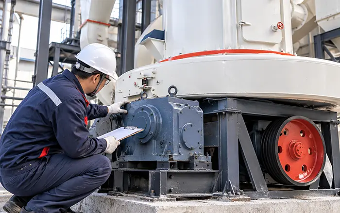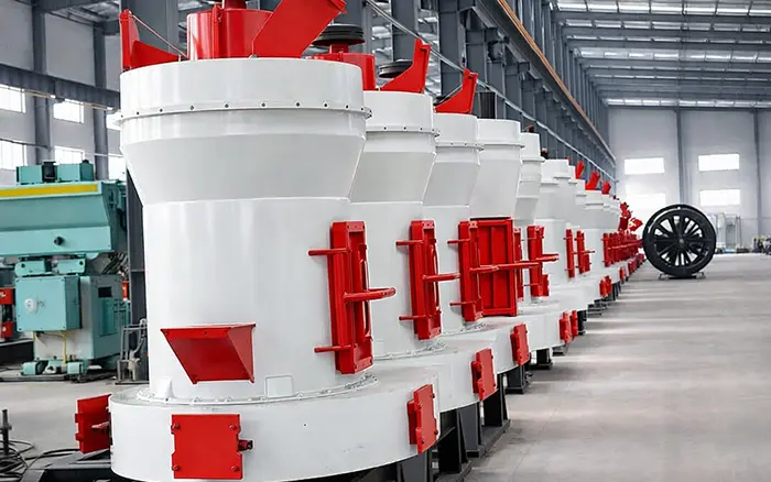
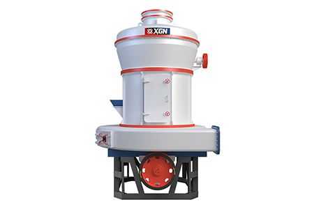
A Raymond mill consists of grinding components, rotating assemblies, airflow equipment, transmission parts and powder-collection devices. Each component performs a specific function, and failure in one area can affect output, product fineness, vibration or energy consumption throughout the system.
Understanding the main Raymond mill parts helps operators:
Identify components correctly
Plan routine inspections
Recognize abnormal wear
Order compatible replacement parts
Reduce unplanned downtime
Avoid replacing serviceable components unnecessarily
Component dimensions, materials and drive arrangements vary between manufacturers and models. Some mills use a belt-and-pulley transmission, while others incorporate a reducer or gearbox. Always confirm the model-specific drawing and parts manual before ordering replacements for a Raymond Mill.
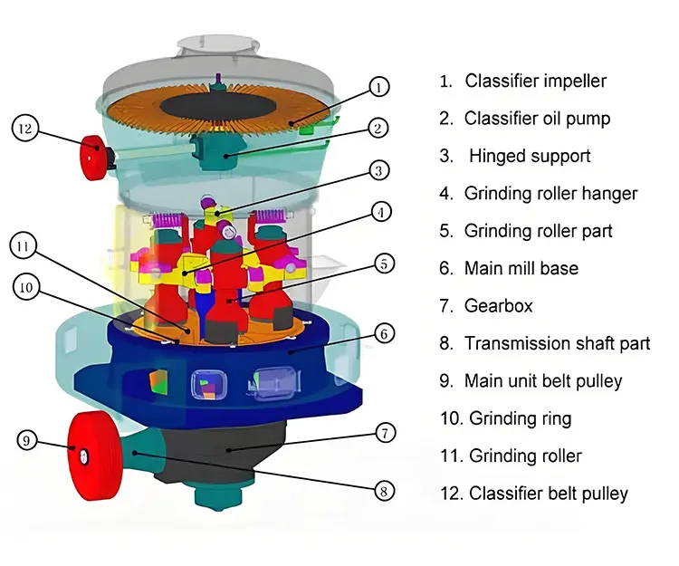
Main Raymond Mill Parts at a Glance
| Part | Main function | Component category |
|---|---|---|
| Grinding rollers | Apply grinding pressure to the material | Wear part |
| Grinding ring | Forms the fixed grinding surface | Wear part |
| Roller arms and assemblies | Support the rollers and transfer centrifugal force | Rotating assembly |
| Main shaft and spider | Rotate and support the roller assemblies | Main rotating component |
| Shovel blades | Lift material into the roller-and-ring grinding zone | Wear part |
| Classifier | Separates qualified fine powder from coarse particles | Classification component |
| Air volute and blower | Move ground material through the airflow circuit | Airflow system |
| Motor and transmission | Provide and transmit power to the main shaft | Drive system |
| Bearings and lubrication system | Support rotation and reduce friction | Support system |
| Mill housing | Enclose and support the internal components | Structural component |
| Feeder and feed pipe | Deliver material into the grinding chamber | Feeding system |
| Cyclone collector | Separate finished powder from circulating air | Collection system |
| Bag filter | Capture remaining fine dust | Dust-control system |
The grinding rollers, grinding ring, shovel blades and some classifier components normally experience the most direct wear. Bearings, shafts, the drive system and housing are not routine wear parts, but they still require inspection.
1. Grinding Rollers
Grinding rollers are among the most important Raymond mill wear parts. During operation, each roller presses against the inner surface of the grinding ring. Material entering the contact zone is compressed, crushed and ground into smaller particles.
Depending on the machine design, the rollers may be mounted on pendulum arms or another form of roller assembly. Centrifugal force moves the rollers outward against the grinding ring as the main shaft rotates.
Common signs of roller wear
Reduced grinding capacity
Uneven roller surface
Grooves or flat areas
Increased vibration
Higher power consumption for the same output
Difficulty maintaining the required product fineness
Uneven wear between individual rollers
Roller material must be selected according to the processed material, operating load and original machine specification. Avoid describing all rollers as high-manganese steel because different models may use high-chromium alloy, alloy steel or another wear-resistant material.
When should grinding rollers be replaced?
Replace or restore the rollers when their profile no longer maintains even contact with the grinding ring or when wear exceeds the limit stated by the manufacturer.
Do not use a fixed operating-hour value for every application. Roller life varies substantially with:
Material hardness
Abrasiveness
Feed particle size
Moisture content
Foreign metal contamination
Feed stability
Required powder fineness
Roller and ring material
2. Grinding Ring
The grinding ring is the fixed circular surface against which the rollers press the material. It is mounted inside the lower section of the mill housing and works together with the rollers to form the main grinding zone.
Roller and ring condition should always be assessed together. Installing new rollers against a severely grooved or uneven ring can produce poor contact and accelerate wear.
Common signs of grinding ring wear
Deep or uneven grooves
Loss of the original grinding profile
Uneven contact marks
Reduced capacity
Coarser finished powder
Increased vibration
Rapid wear of newly installed rollers
The ring should be replaced when its dimensions or surface condition no longer allow correct roller contact. Use model-specific measurements rather than a universal groove-depth threshold.
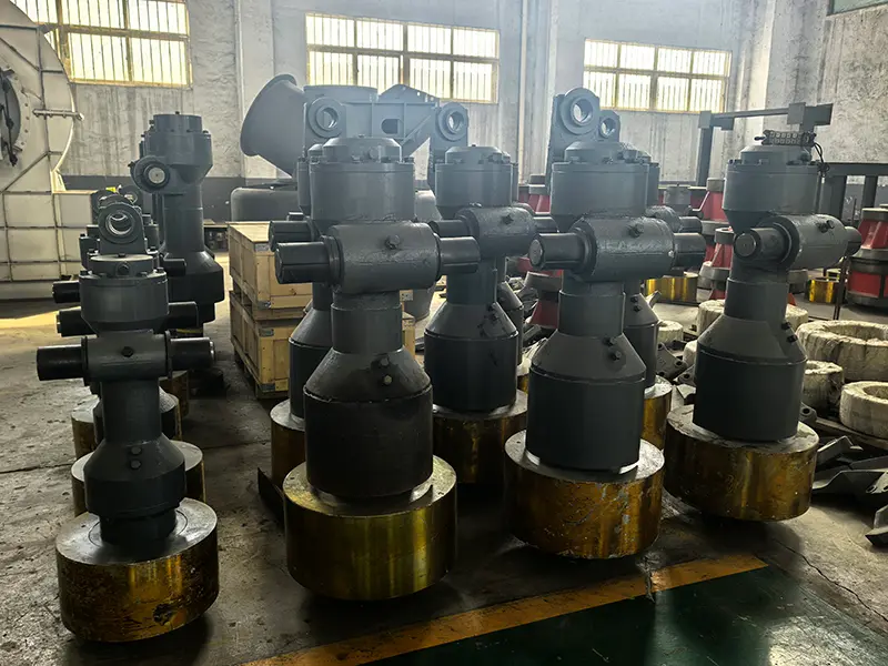
3. Roller Arms and Roller Assemblies
The roller assembly connects each grinding roller to the rotating support structure. Depending on the mill design, it may include:
Roller arm
Roller shaft
Roller bearing
Bearing housing
Bushings
Seals
Retaining components
The assembly allows the roller to rotate while also moving outward against the ring.
Inspection points
Check for:
Bearing noise or excessive temperature
Loose fasteners
Seal damage
Lubricant leakage
Excessive radial or axial clearance
Cracks in the roller arm
Uneven movement between roller assemblies
A damaged roller bearing can create vibration and uneven roller pressure even when the roller surface still appears usable.
4. Main Shaft and Spider Assembly
The main shaft transfers rotational force to the roller-support structure. The upper support is sometimes referred to as a spider, plum frame or roller hanger assembly, depending on the machine design and manufacturer.
The main shaft must remain correctly aligned because shaft runout or bearing wear can affect every roller simultaneously.
Warning signs
Movement or looseness at the shaft
Abnormal vibration
Uneven roller contact
Noise from the shaft-bearing area
Repeated seal leakage
Unstable main-unit speed
The main shaft is not normally replaced according to operating hours. Replacement is based on dimensional inspection, cracks, excessive wear, deformation or damage to bearing and seal surfaces.
5. Shovel Blades
Shovel blades, also called plows or scraper blades, rotate below the grinding zone. Their function is to lift material from the bottom of the mill and deliver it into the gap between the rollers and grinding ring.
They do not simply push finished powder toward the airflow system. Their main role is to maintain a continuous supply of material to the grinding contact zone.
Signs of shovel-blade wear
Material accumulation at the bottom of the mill
Reduced quantity of material entering the grinding zone
Unstable output
Uneven grinding
Worn, shortened or deformed blade tips
Contact between the blade and surrounding components
Shovel blades should be inspected as a set. Uneven blade dimensions may distribute material unevenly around the grinding ring.
6. Classifier
The classifier is located above the grinding chamber. It separates particles according to the required product size.
Qualified fine particles pass through the classifier and continue to the collection system. Oversized particles are rejected and return to the grinding zone.
The classifier may contain:
Classifier rotor
Blades or vanes
Drive motor
Variable-frequency drive
Shaft
Bearings
Housing
Adjustment system
In many dynamic classifier designs, increasing classifier speed produces a finer product, while reducing speed allows coarser particles to pass. The exact relationship should be confirmed for the specific machine.
Classifier problems that affect product quality
Worn or deformed blades
Material buildup on the rotor
Uneven blade spacing
Damaged bearings
Incorrect rotation speed
Air leakage
Unstable airflow
Incorrect variable-frequency drive settings
Do not replace classifier blades based only on operating hours. Inspect their shape, balance, mounting and effect on finished-product particle size.
7. Air Volute and Blower
The air volute directs airflow through the mill body. The blower supplies the airflow required to move ground particles from the grinding chamber to the classifier and collection system.
These components influence:
Powder conveying
Classification stability
System pressure
Collection efficiency
Dust control
Common inspection points
Dust buildup inside the air passage
Worn or damaged fan impeller
Fan imbalance
Loose connections
Air leakage
Blocked ducts
Abnormal bearing temperature
Unstable airflow
A reduction in output or poor classification is not always caused by worn rollers. Restricted ducts, fan problems or system leakage can produce similar symptoms.
8. Motor and Transmission System
The drive system supplies power to the main shaft. Its configuration varies by machine model.
It may include:
Electric motor
Drive pulley
V-belts
Coupling
Gear reducer
Transmission shaft
Protective guards
Do not assume that every Raymond mill uses an integrated gearbox. Confirm whether the specific model uses a reducer, direct coupling or pulley transmission.
Belt-and-pulley system inspection
Check:
Cracked or hardened belts
Uneven belt tension
Pulley-groove wear
Pulley alignment
Belt slippage
Loose guards
Shaft runout
Gearbox or reducer inspection
Check:
Oil level and condition
Leakage
Temperature
Noise
Vibration
Breather condition
Shaft alignment
Detailed gearbox fault diagnosis should remain on the separate raymond mill gearbox repair page. This article should only identify the gearbox as part of the transmission system.
9. Bearings and Lubrication Components
Bearings support the main shaft, roller shafts, classifier shaft, fan and transmission components. Their size, type and lubrication method depend on the model.
Common associated parts include:
Rolling bearings
Bearing housings
Grease lines
Oil lines
Seals
Labyrinth seals
Oil-level indicators
Lubrication pumps
Signs of bearing problems
Rising operating temperature
Abnormal noise
Increased vibration
Excessive shaft movement
Dark or contaminated lubricant
Metal particles
Repeated seal failure
High temperature does not automatically mean that the bearing must be replaced. Overlubrication, incorrect lubricant, misalignment and excessive preload can also cause heating.
10. Mill Housing and Inspection Doors
The mill housing supports and encloses the internal grinding components. It also guides airflow through the grinding and classification zones.
Inspect the housing for:
Cracks
Loose fasteners
Deformation
Damaged inspection-door seals
Air leakage
Dust leakage
Contact marks from rotating components
The housing is normally a long-life structural part. Damage to it may indicate foundation movement, prolonged vibration, foreign-object impact or internal component misalignment.
11. Feeding System
The feeding system normally includes:
Feed hopper
Vibrating feeder or screw feeder
Feed chute
Feed pipe
Gate or flow-control device
Its job is to deliver a stable quantity of material into the mill.
Excessive feeding may overload the grinding chamber, while insufficient or unstable feeding reduces capacity and can produce inconsistent operation.
Check for:
Blocked feed chutes
Worn feeder surfaces
Loose feeder components
Unstable feeder speed
Oversized feed
Metal contamination
Moist or sticky material buildup
Feed size should always remain within the limit specified for the exact mill model. Do not use a single universal feed-size limit for all Raymond mills.
12. Cyclone Collector and Bag Filter
The cyclone collector and bag filter are not internal mill components, but they are essential parts of the complete Raymond grinding system.
Cyclone collector
The cyclone uses centrifugal airflow to separate finished powder from the conveying air. Inspect it for:
Internal wear
Material buildup
Air leakage
Blocked discharge
Damaged rotary valve
Worn seals
Bag filter
The bag filter captures fine residual particles before the air is discharged or recirculated.
Inspect:
Filter bags
Bag cages
Pulse-cleaning valves
Differential pressure
Hopper discharge
Dust leakage
Air connections
A blocked filter can restrict airflow and reduce the performance of the complete grinding system.
Raymond Mill Wear Parts and Replacement Indicators
Fixed replacement intervals are unreliable because operating conditions vary. Use condition-based inspection wherever possible.
| Part | Main wear or failure signs | Recommended response |
|---|---|---|
| Grinding rollers | Flat areas, grooves, reduced output, uneven wear | Measure the roller profile and compare it with the manufacturer’s limit |
| Grinding ring | Deep grooves, uneven surface, poor roller contact | Inspect with the rollers and replace when correct contact cannot be restored |
| Shovel blades | Shortened tips, deformation, poor material lifting | Replace as a balanced set where required |
| Classifier blades | Deformation, buildup, imbalance, poor fineness control | Clean, measure and replace damaged blades |
| Roller bearings | Heat, noise, vibration, excessive clearance | Check lubrication, alignment and bearing condition |
| V-belts | Cracks, glazing, slippage, unequal tension | Replace with a correctly matched belt set |
| Shaft seals | Oil leakage, dust entry, hardened sealing lip | Replace and inspect the shaft contact surface |
| Fan impeller | Erosion, buildup, vibration, imbalance | Clean, balance, repair or replace according to condition |
| Filter bags | High pressure drop, tears, dust leakage | Clean or replace damaged bags |
| Couplings | Worn elements, looseness, misalignment | Correct alignment and replace worn components |
How to Order the Correct Raymond Mill Parts
“Raymond mill” is a general equipment name, not a complete part specification. Similar-looking parts may have different dimensions, materials and fits.
Provide the following information when requesting replacement parts:
Mill manufacturer
Exact model
Equipment serial number
Part name and installation position
Part number, if available
Technical drawing or measured dimensions
Material specification
Motor power and operating speed
Photographs of the original part
Photographs of the damage or wear pattern
Processed material
Required powder fineness and operating capacity
For grinding rollers and rings, also provide:
Outside diameter
Inside diameter
Width or height
Mounting dimensions
Surface profile
Material specification
Hardness requirement, if known
Do not rely only on a photograph when ordering critical rotating or load-bearing components.
Common Mistakes When Replacing Raymond Mill Parts
Replacing only one severely worn roller
A single new roller may not share load evenly with several heavily worn rollers. Inspect the complete roller set and ring before deciding what to replace.
Installing new rollers against a worn ring
The new roller surface may contact only part of the old ring profile, producing concentrated pressure and rapid wear.
Selecting parts by machine name only
Different manufacturers may use the same general “Raymond mill” name but completely different dimensions and drive arrangements.
Ignoring the cause of abnormal wear
Uneven wear may result from unstable feeding, bearing clearance, shaft misalignment or material distribution. Installing new parts without correcting the cause can lead to repeat failure.
Using unverified wear thresholds
A universal groove depth or operating-hour limit should not replace the manufacturer’s dimensional specification.
Reusing contaminated lubricant
Particles left after bearing or gear damage can rapidly damage newly installed components.
How to Extend Raymond Mill Parts Service Life
Keep the feed within the model-specific size limit.
Prevent metal and foreign objects from entering the mill.
Maintain a stable feed rate.
Avoid processing materials beyond the specified hardness and moisture limits.
Use the lubricant recommended for each bearing and transmission component.
Keep the classifier rotor and blades clean.
Inspect rollers and the ring as a matched grinding pair.
Maintain correct belt, coupling and shaft alignment.
Clean ducts, cyclone collectors and filters before airflow becomes restricted.
Record temperature, vibration, output and product fineness under comparable conditions.
Investigate sudden changes instead of waiting for a major breakdown.
Conclusion
Understanding the function and wear characteristics of Raymond mill parts helps operators plan inspections, identify abnormal conditions and order compatible replacement components.
The grinding rollers and grinding ring form the main grinding pair, while the shovel blades supply material to the grinding zone. The classifier, blower, cyclone collector and bag filter control powder separation and transport. Bearings, shafts and transmission parts keep the system operating reliably.
Replacement decisions should be based on measurements, operating condition and model-specific limits—not universal operating hours. When requesting parts, provide complete equipment and component information to reduce installation errors and repeat failures.
For model selection, capacity and complete-machine configuration, see the Raymond Mill for Sale guide.